
Surge voltage protector having an insulating sheath

A varistor, armored technology, applied in the direction of overvoltage protection resistors, varistors, etc., can solve problems such as affecting the mechanical strength of fixed components, and achieve the effect of avoiding overload

Inactive Publication Date: 2013-11-20
SIEMENS AG
View PDF1 Cites 0 Cited by
  • Summary
  • Abstract
  • Description
  • Claims
  • Application Information

AI Technical Summary

Problems solved by technology

This results in a bent position which adversely affects the mechanical strength of the fixing element

Method used


Image

  • Surge voltage protector having an insulating sheath
  • Surge voltage protector having an insulating sheath
  • Surge voltage protector having an insulating sheath

Examples


Embodiment Construction

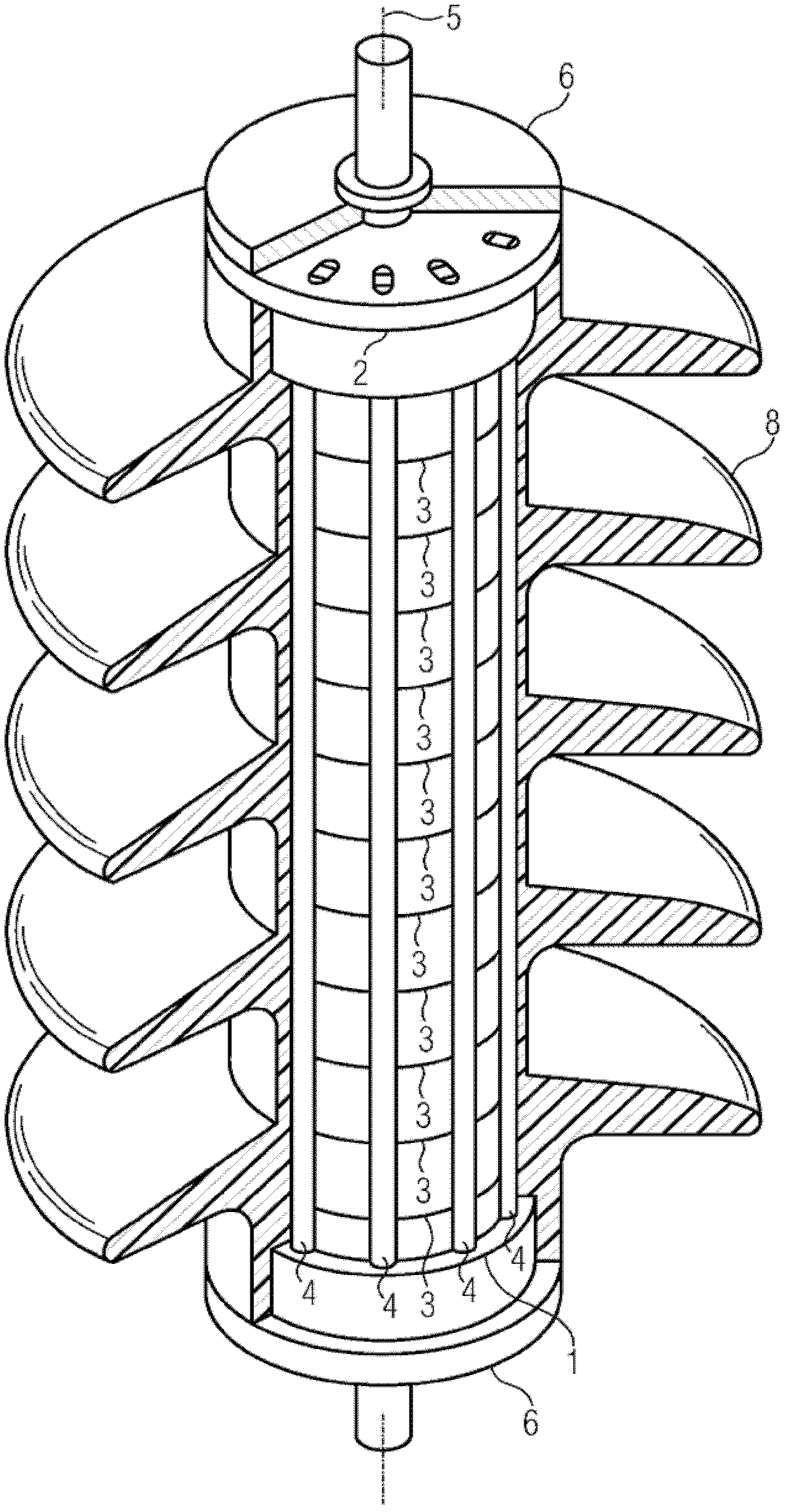
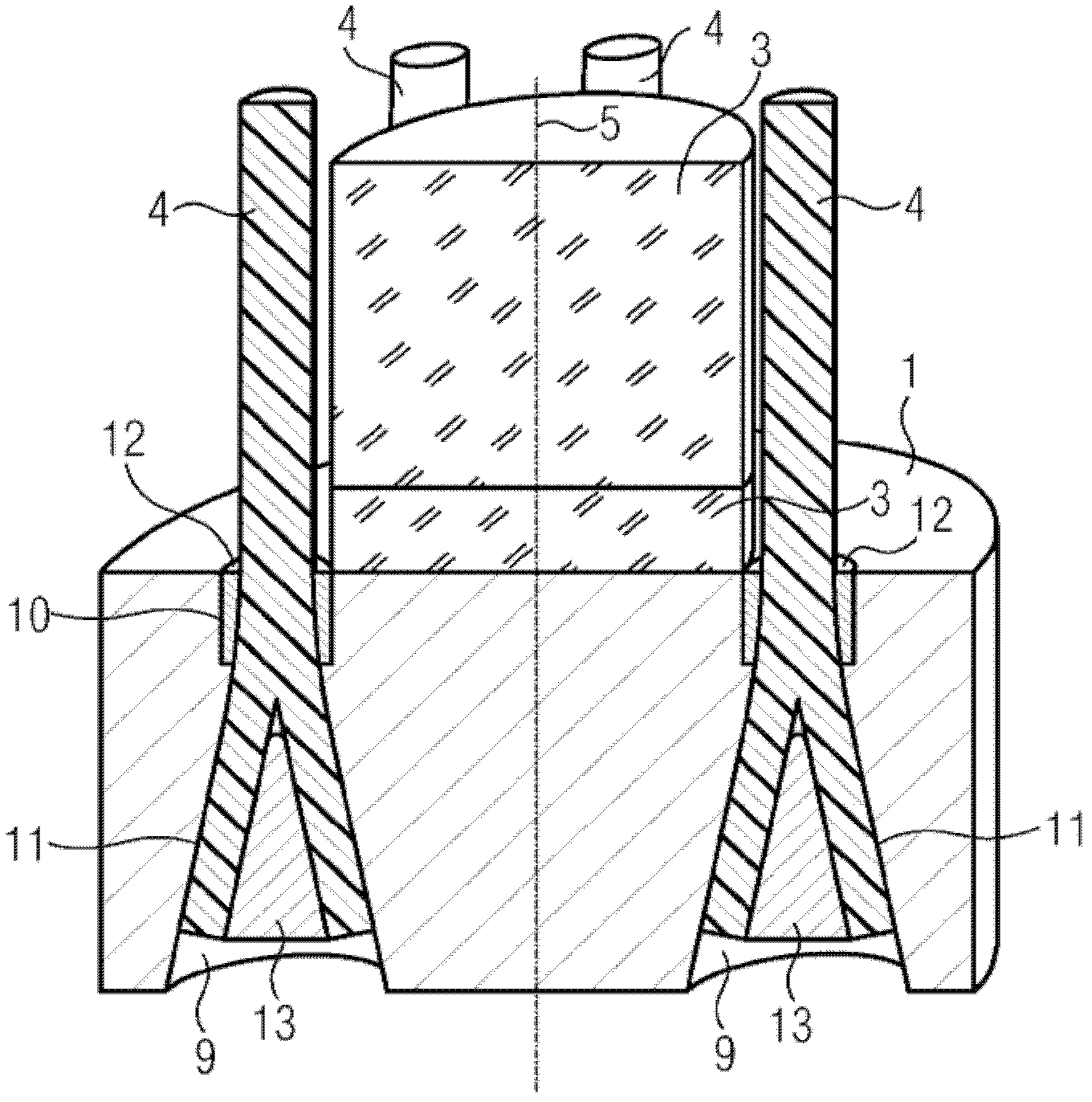
[0035] figure 1 An impedance device in the form of a surge protector is shown. The surge voltage protector has a first armor body 1 and a second armor body 2 . The two sheathing bodies 1 , 2 are identically shaped and delimit a resistive body. The resistive body is a varistor having a stack of individual elements 3 . The individual elements 3 are preferably cylindrically shaped and have rounded end faces. The end faces of the individual elements 3 abut against each other in an electrically conductive manner. Here, the height of the individual elements 3 is variable. The individual elements 3 , which are arranged respectively on the end faces, rest in an electrically conductive manner on the contact surfaces of the two armor bodies 1 , 2 . The individual elements 3 are in electrically conductive contact with each other and with the armor bodies 1 , 2 , possibly with contact bodies arranged in between. The armor body 1 , 2 consists of an electrically conductive material, f...


PUM


Abstract

The invention relates to an impedance assembly having a first armature body (1) and a second armature body (2). An impedance body is arranged between the two armature bodies (1, 2). The impedance body is braced between the armature bodies (1, 2) by means of a retaining element (4). The retaining element (4) has a radially expanded section. The radially expanded section is limited by an expansion limitation element (12).

Description

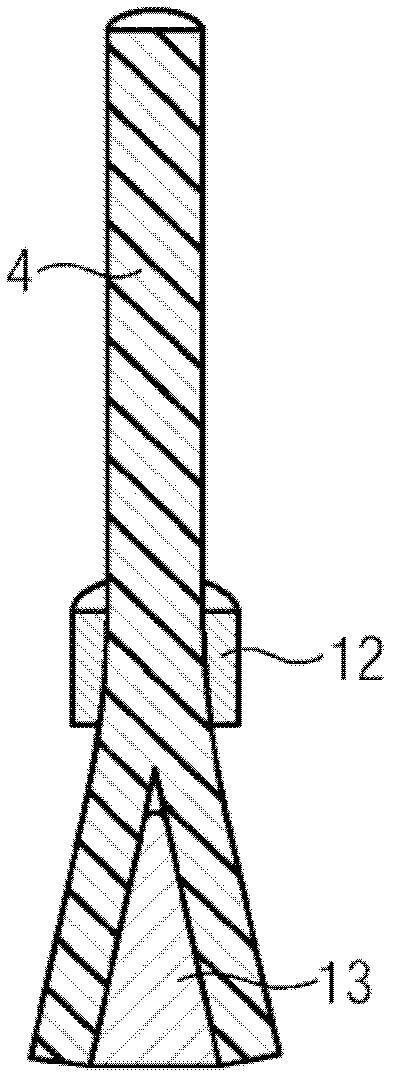
technical field [0001] The invention relates to an impedance arrangement having a first and a second armor body, which are connected to one another with an interposition of the impedance body by means of a fastening element having end-side radially widened sections. Background technique [0002] Such an impedance arrangement is known, for example, from patent document DE 10 2006 003 576 B4. The impedance device therein has a first and a second armor body, which are connected by means of a fixing element with an impedance body interposed therebetween. Known fastening elements are provided with radially widened sections on the end faces. To produce the radial widening, a wedge is driven in, which diverges the fastening element and thus clamps it into the groove of the armor body. [0003] By diverging from one another, the fastening element engages in the structure and thus achieves a deformation of the fastening element. This results in bent positions which adversely affec...

Claims


Application Information

Patent Timeline
Patent Type & Authority Patents(China)
IPC IPC(8): H01C7/12
CPCH01C7/12
Inventor 伯恩德.克鲁斯卡德克.斯普林伯恩
Owner SIEMENS AG
Learn More