
Wireless communication system and communication control method

A technology of wireless communication system and control device, which is applied in wireless communication, radio transmission system, diversity/multi-antenna system, etc., can solve the problems of not yet proposed communication steps, not proposed, antenna selection, etc., so as to improve frequency utilization efficiency, reduce Small differences, the effect of improving communication quality

Inactive Publication Date: 2011-12-28
HITACHI LTD
View PDF5 Cites 18 Cited by
  • Summary
  • Abstract
  • Description
  • Claims
  • Application Information

AI Technical Summary

Problems solved by technology

In the existing protocol, the terminal can only use one cell as the serving cell, and only use the antenna in the cell (with the RRU controlled by a baseband modem) to communicate, and cannot select antennas across multiple cells
[0014] However, no specific communication steps have been proposed to select antennas across multiple cells for network MIMO
In particular, it is very important to select the best antenna for the terminal without being restricted by the framework of the cell, which is very important for generating the effect of network MIMO, but no specific method for this antenna selection has been proposed
That is, in the prior art, no specific steps have been proposed to improve the communication quality of terminals near the cell border by allocating antennas of multiple base stations to the terminals near the cell border

Method used


Image

  • Wireless communication system and communication control method
  • Wireless communication system and communication control method
  • Wireless communication system and communication control method

Examples


no. 1 Embodiment approach

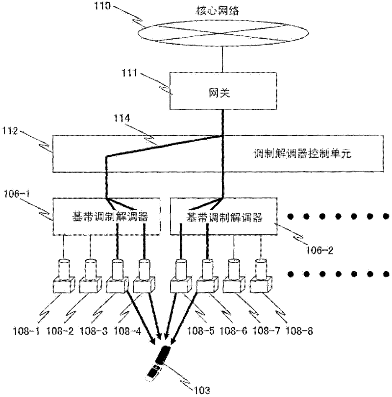
[0060] figure 1 It is a diagram showing the network configuration of the wireless communication system according to the first embodiment.

[0061] The wireless communication system of the first embodiment includes a gateway 111, a modem control unit 112, baseband modems 106-1, 106-2, ... (hereinafter referred to simply as 106 when there is no need to distinguish the baseband modems), and an RRU (Remote Radio Unit: remote wireless unit) 108-1, 108-2, . The radio communication system of this embodiment has a plurality of baseband modems 106 , but may have one baseband modem 106 . Furthermore, the wireless communication system according to the present embodiment has a plurality of RRUs 108 , but when there are a plurality of baseband modems 106 , one RRU 108 may be provided for each baseband modem 106 .

[0062] The gateway 111 is a node that connects the core network 110 and the radio access network (lower layer of the gateway 111 ) and terminates the radio access network, an...

no. 2 Embodiment approach

[0203] Figure 22 It is a diagram showing the network configuration of the radio communication system according to the second embodiment of the present invention.

[0204] The wireless communication system of the second embodiment is different from the wireless communication system of the first embodiment in which the baseband modem 106 and the RRU 108 are connected in a predetermined correspondence relationship, in that a modem-RRU switch 113 is provided between the baseband modem 106 and the RRU 108 . In addition, only the differences from the aforementioned first embodiment will be described regarding the second embodiment, and the description of the same configuration and processing as those of the aforementioned first embodiment will be omitted.

[0205] The modem-inter-RRU switch 113 switches the switch according to the instruction from the modem control unit 112 to switch the connection between one or more antenna ports of the baseband modem 106 and the RRU 108 . The w...


PUM


Abstract

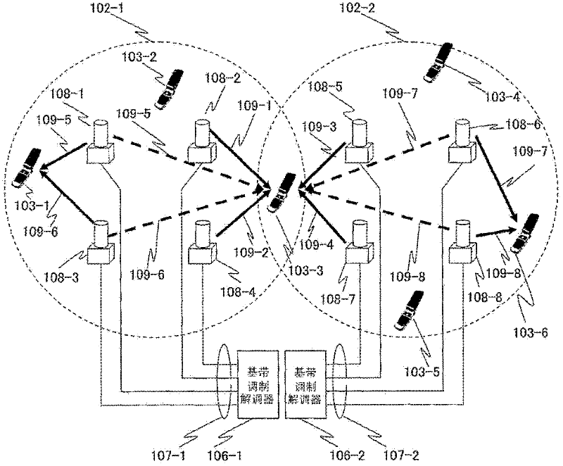
In a wireless communication system, a plurality of base stations each comprise a plurality of cells and a terminal communicates with the base stations. Each of the base stations is equipped with one or a plurality of antennas. The base stations transmit first reference signals that do not overlap with at least those of neighborhood base stations and are unique to the antennas. The terminal receives the first reference signals, estimates the reception powers of the first reference signals transmitted from the respective antennas, selects, based on the estimation results of the reception powers, a plurality of the antennas suitable for communication, and transmits the antenna selection results to the base stations. The base stations refer to the antenna selection results transmitted from the terminal to assign the antennas belonging to the different cells to the terminal and notify the terminal of the results of assigning the antennas.

Description

technical field [0001] The present invention relates to a wireless communication system, in particular to a wireless communication system in which a terminal communicates with multiple base stations. Background technique [0002] Figure 31 It is a figure explaining the existing cellular system. [0003] Two base stations (101-1, 101-2) respectively form cells (102-1, 102-2). The three terminals (103-1, 103-2, 103-3) in the cell 102-1 communicate with the base station 101-1, and the three terminals (103-4, 103-5, 103- 6) Communicate with the base station 101-2. [0004] Each base station and each terminal has multiple antennas. Each base station performs MIMO (Multiple Input Multiple Output) communication with one terminal belonging to a cell formed by the base station at a certain moment. In addition, in a multi-carrier communication system such as OFDMA (Orthogonal Frequency Division Multiple Access: Orthogonal Frequency Division Multiple Access), each carrier is ortho...

Claims


Application Information

Patent Timeline
Patent Type & Authority Applications(China)
IPC IPC(8): H04W16/28H04W88/02
CPCH04B7/061H04B7/024
Inventor 藤岛坚三郎小野豪高田芽衣上野幸树
Owner HITACHI LTD
Learn More