Consumable-free self-connection construction method for light steel keels

A construction method and light steel keel technology, applied in the field of building decoration and decoration, can solve the problems of low construction efficiency, poor construction site environment, large consumption of auxiliary materials, etc., and achieve high construction efficiency and no construction noise. Effect

Inactive Publication Date: 2012-01-04
JIANGSU JIAYANGHUALIAN BUILDING & DECORATION CO LTD
View PDF3 Cites 1 Cited by
  • Summary
  • Abstract
  • Description
  • Claims
  • Application Information

AI Technical Summary

Problems solved by technology

[0003] The above-mentioned construction methods have the following defects, which are not limited to those listed: First, they are critical to the conditions of the construction site, because whether self-tapping screws or core-pulling Whether the rivets are connected or fixed with special clips, it is necessary to use electric tools such as pistol drills or similar drilling devices to drill holes on the keel, and the drilling devices must be supported by a power source, otherwise construction will not be possible
However, in the decoration and decoration construction site, not only the power supply is not normal, either there is a power outage, or the power supply is far away from the work site and needs to be fed by lengthy cables; secondly, the consumption of auxiliary materials is large, which leads to increased construction costs, such as The use of self-tapping screws, blind rivets and / or special clips will undoubtedly consume fasteners, which will lose the economy of construction operations and is not compatible with the economical and energy-saving spirit advocated by the whole society; the third , the construction efficiency is low, which affects the progress of the project. Therefore, if the two keels are to be fixedly connected to each other, the process of drilling and fastener connection is required; The nail shank that comes off on the blind rivet is bent down, which makes the construction site unsightly; fifth, it wastes energy and loses safety, and the labor intensity of the constructor is high and also accompanied by noise pollution, because the drilling of the keel drilling The hole device needs to consume electric energy, and because the operator's limbs will be damaged if the drilling device is not operated carefully, and because the constructor needs to continuously exert a large force in the process of drilling the fixed connection hole for the keel with the drilling device force

Method used


Image

  • Consumable-free self-connection construction method for light steel keels
  • Consumable-free self-connection construction method for light steel keels
  • Consumable-free self-connection construction method for light steel keels

Examples


Embodiment 1

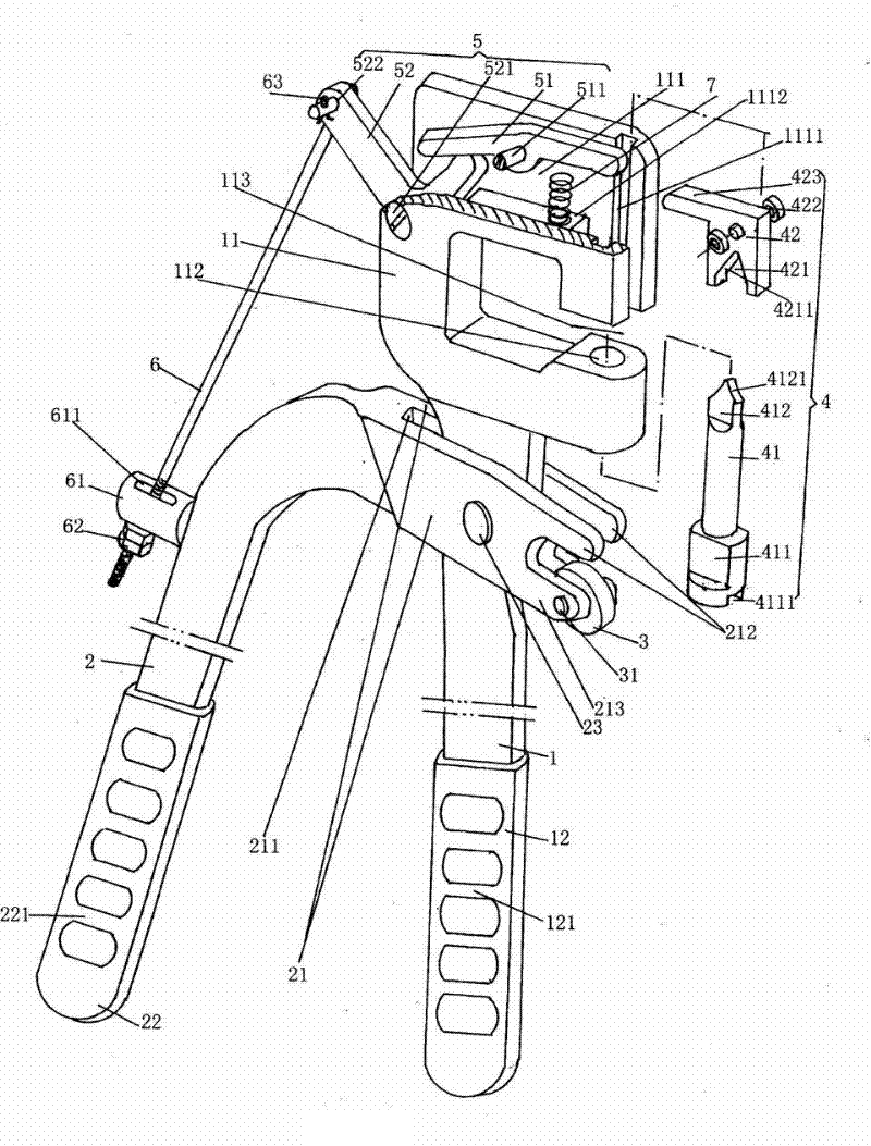
[0034] Please see figure 1 with figure 2 .

[0035] A) Equipped with a handheld riveting pliers, the specific structure of the handheld riveting pliers figure 1 Reveal, see figure 1 , A first handle 1 is given. Considering the comfort when gripping in use, a non-metallic first sheath 12 is added to the lower part of the first handle 1, which is preferably not limited to The material of the first sheath 12 is plastic or nylon or rubber. In this embodiment, plastic is selected, and a first non-slip flange 121 is also formed on the surface of the first sheath 12; the upper part of the first handle 1 is formed as a clamp The pliers head 11 is provided with a pliers head slot 111, which can also be called a pliers head cavity; the middle part of the first handle 1 is hinged with the second handle 2 which will be described in detail below Connected. At present figure 1 The position state shown is an example (the same below). A guide pulley groove 1111 is provided on a pair of gr...

Embodiment 2

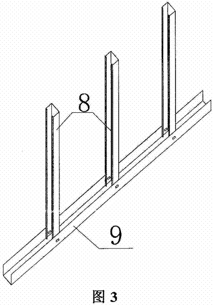
[0043] Please see image 3 .

[0044] In step B), the vertical keel is used as the first keel 8 and the ground keel is used as the second keel 9, and the end of the first keel 8 is overlapped with the second keel 9. The rest are the same as the description of Embodiment 1.

Embodiment 3

[0046] Please see Figure 4 .

[0047] In step B), the two vertical keels that need to be connected are used as the first keel 8, the connecting keel for connecting the two vertical keels is used as the second keel 9, and one end (upper end) of the second keel 9 is connected to The upper first keel 8 of the two first keels 8 overlaps, and the other end (lower end) of the second keel 9 is overlapped with the lower first keel 8 of the two first keels 8. The rest are the same as the description of Embodiment 1.


PUM


Abstract

The invention relates to a consumable-free self-connection construction method for light steel keels, belonging to the technical field of building decoration and trim. The method comprises the following steps of: providing a handheld riveting clamp, wherein the handheld riveting clamp comprises a first handle, a second handle, a mold mechanism made by the cooperation of a male die and a female die, an ejection member, a female die driving mechanism, a tension rod and an elastic member; preparing before riveting, wherein riveting parts of a first keel and a second keel which are needed to be riveted together are mutually superposed by an operator; and riveting, wherein the first handle and the second handle are respectively held by the hands of the operator, so that the female die is in contact with the first keel, the male die is in contact with the second keel, the first keel and the second keel are pierced through the cooperation of the male die and the female die, the tension rod is used for acting on the female die driving mechanism, the female die driving mechanism is used for pressing the female die, and then turned-over edges which are formed at the pierced parts of the first keel and the second keel can be combined together in a superposing state. The consumable-free self-connection construction method for the light steel keels has the advantages of high construction efficiency and no construction noise and ensures that the construction site environment is clean and tidy and the work intensity for operators is low.

Description

technical field [0001] The invention belongs to the technical field of building decoration construction, and in particular relates to a self-connecting construction method for light steel keels without consumable materials. Background technique [0002] The light steel keel is the carrier for building a lightweight partition wall, that is to say, in the process of building a lightweight partition wall, it is first necessary to build a light steel keel bracket. In the prior art, when constructing light steel keels, more specifically, such as fixing the ground keel and the top keel to the main structure of the building, connecting the longitudinal (vertical) keel to the ground keel and the top keel, and In the process of connecting the center keel to the vertical keel, connecting the cross brace (horizontal) keel to the vertical (longitudinal) keel, and even processing the door opening, installing junction boxes and wiring pipes, people often use automatic Tapping screw conne...

Claims


Application Information

Patent Timeline
Patent Type & Authority Applications(China)
IPC IPC(8): B21D39/00
Inventor 张建忠周健沈菊芳钱瑛黄健
Owner JIANGSU JIAYANGHUALIAN BUILDING & DECORATION CO LTD
Why Eureka
Try Eureka