
Folding protection wall capable of being removed quickly

A protective wall and folding technology, applied in protective equipment, dikes, coastline protection, etc., can solve problems such as filling, limited scope of application, and materials that cannot be lifted together

Active Publication Date: 2012-01-04
中国人民解放军63983部队
View PDF7 Cites 6 Cited by
  • Summary
  • Abstract
  • Description
  • Claims
  • Application Information

AI Technical Summary

Problems solved by technology

However, since this folding protective wall is only composed of several unit protective walls composed of side nets and side nets, each unit protective wall has no bottom plate. Filling with sand, soil, stones and other waste materials, it is not possible to fill sand, soil, stones and other waste materials in places other than the exact location of the installation site before hoisting to the required position
Especially when setting up a protective wall with a height of more than two floors, the setting time will be prolonged due to insufficient sand, soil, stone and other convenient materials on site, which cannot meet the rapid requirements of wartime
And because this folding protective wall has no bottom plate, not only the sand, soil, stones and other materials filled during withdrawal cannot be hoisted together, but also the sand, soil, stones and other materials in it are easy to be lifted when used as a flood embankment. flooded from its bottom
Therefore, this folding protective wall can only be used in the protection of military targets, and cannot be used in flood fighting and emergency situations, and its scope of application is limited.

Method used


Image

  • Folding protection wall capable of being removed quickly
  • Folding protection wall capable of being removed quickly
  • Folding protection wall capable of being removed quickly

Examples


Embodiment Construction

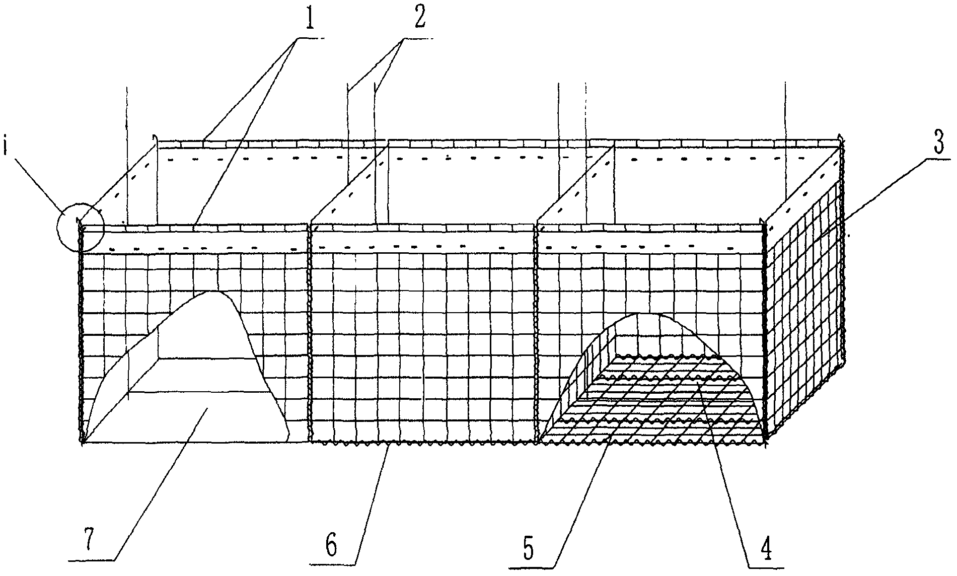
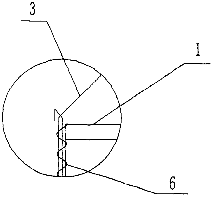
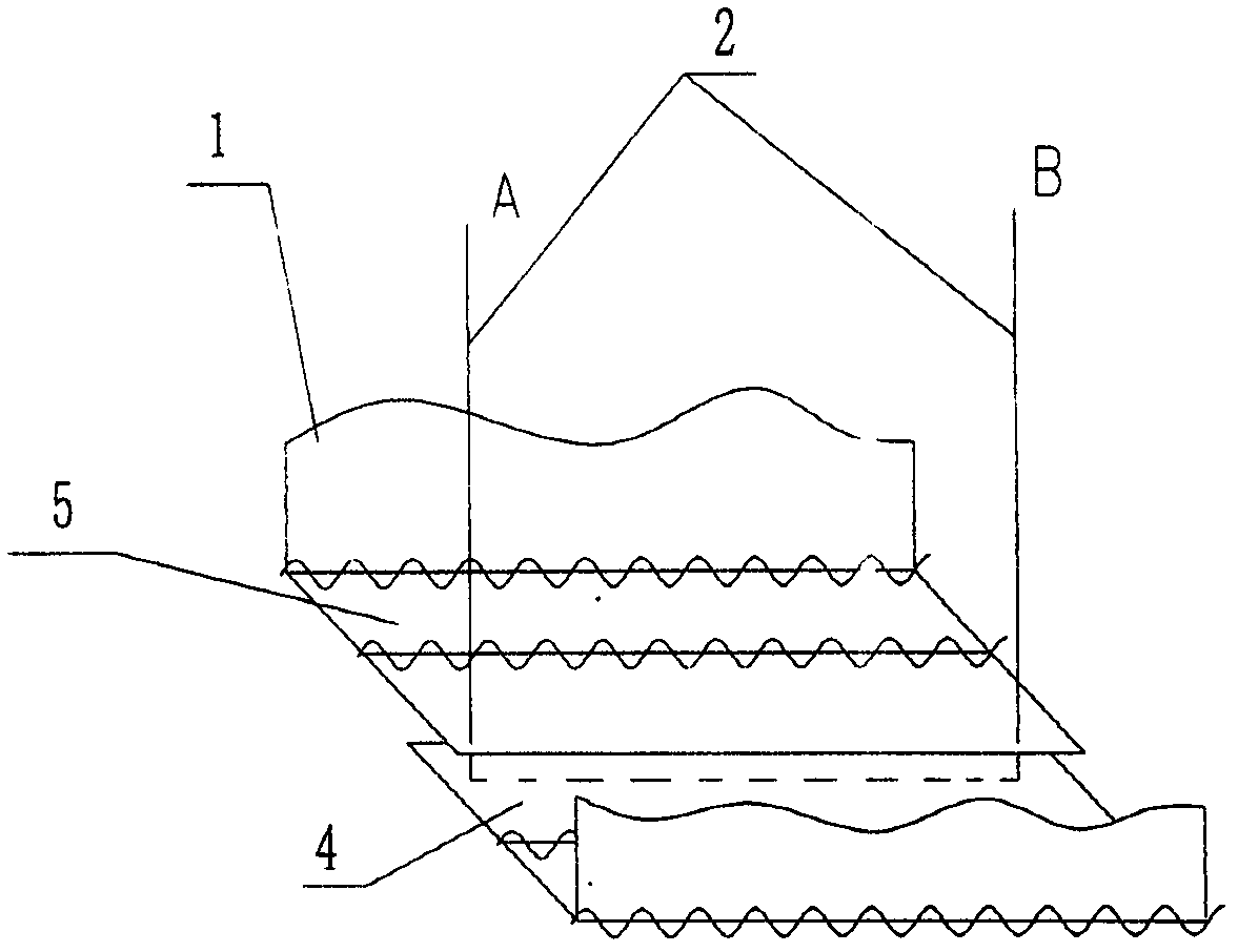
[0016] like figure 1 and figure 2 As shown, the rapidly retractable collapsible protective wall of the present invention is composed of three unit protective walls. The unit protective wall includes two side mesh sheets 3 and two side mesh sheets 1, and the side mesh sheets 3 and the side mesh sheets 1 have the same height. The two vertical sides of the two side mesh sheets 3 are respectively connected with the two vertical sides of the two side mesh sheets 1 in a foldable manner by means of a screw connection frame 6 . like figure 2 As shown, the helical connecting frame 6 is made of steel wire. Each unit protective wall is lined with an inner lining 7, which is sewn from geotextile, and its shape is adapted to the inner cavity of the unit protective wall. In order to facilitate the lifting of the sand, soil, stone and other materials in the protective wall together, a bottom mesh is arranged between the side mesh 3 and the bottom edge of the side mesh 1. like image ...


PUM


Abstract

The invention relates to a folding protection wall capable of being removed quickly, which comprises at least two unit protection walls, wherein each unit protection wall comprises two side meshes and two edge meshes, two vertical edges of the two side meshes are connected with two vertical edges of the two edge meshes respectively in a foldable way, and an inner lining is arranged in each unit protection wall. The folding protection wall is characterized in that bottom meshes are arranged among bottom edges of the side meshes and the edge meshes, wherein each bottom mesh comprises a first half mesh and a second half meshes which are both rectangular, have the same length and as long as the horizontal length of each edge mesh, one long edge of each of the first half mesh and the second half mesh are respectively connected with bottom edges of adjacent two meshes in a foldable way. When the folding protection wall is in use, the adjacent edges of the first half mesh and the second half mesh are overlapped, and the two ends of each overlapped edge are both connected with a hoisting steel rope. The folding protection wall has a wide application range and can be used as a protection wall of a temporary protecting embankment for fighting against flood or a protection wall of a military target.

Description

technical field [0001] The present invention relates to a protective wall. Specifically, it is a protective wall used to build a temporary protective embankment during flood fighting and emergency rescue. It can also be used as protection for military targets. Background technique [0002] In wartime, in order to protect various military targets from enemy attacks, protective measures are mostly taken around military targets. The most commonly used protective measure is to stack sandbags around or above military targets to enhance the protection capability of military targets. Although this measure can enhance the protection capability of military targets, because the filling and handling of sandbags mainly rely on manpower, which requires a lot of manpower and takes a long time to build, it is difficult to meet the requirements of rapid setting in wartime. [0003] In order to adapt to the rapid requirements of wartime, the American company HESCO developed a folding prot...

Claims


Application Information

Patent Timeline
IPC IPC(8): E02B3/10F41H5/24
Inventor 韩军陈高杰王红坚张欲保朱保国吴继斌李威潘晟菡冯继新
Owner 中国人民解放军63983部队
Learn More