
Slewing bearing ball belt-type locating retainer

A technology of slewing bearing and cage, which is applied to bearing components, shafts and bearings, mechanical equipment, etc., can solve the problems of limited use range of slewing bearings, increased circumferential gap between balls, and noise caused by collision of isolation blocks, and achieves expanded use. The effect of improving performance such as field, starting torque and noise, and prolonging the service life

Active Publication Date: 2013-01-09
MAANSHAN FY PRECISION MACHINERY CO LTD
View PDF5 Cites 0 Cited by
  • Summary
  • Abstract
  • Description
  • Claims
  • Application Information

AI Technical Summary

Problems solved by technology

[0002] The existing four-point contact single row ball type slewing bearing, its rolling elements (balls) are usually isolated by spacer blocks, but the existing spacer blocks are prone to wear after long-term use, which increases the circumferential gap between the balls, and the slewing bearing rotates When the isolation block will make collision noise, or even dump and block the raceway, especially when the slewing bearing requires vertical installation, high speed, low starting torque, low noise and long life, the existing isolation block cannot meet these requirements , so that the scope of use of the slewing ring is limited

Method used


Image

  • Slewing bearing ball belt-type locating retainer
  • Slewing bearing ball belt-type locating retainer
  • Slewing bearing ball belt-type locating retainer

Examples


Embodiment Construction

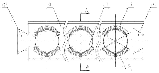
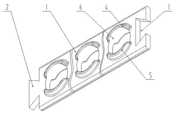
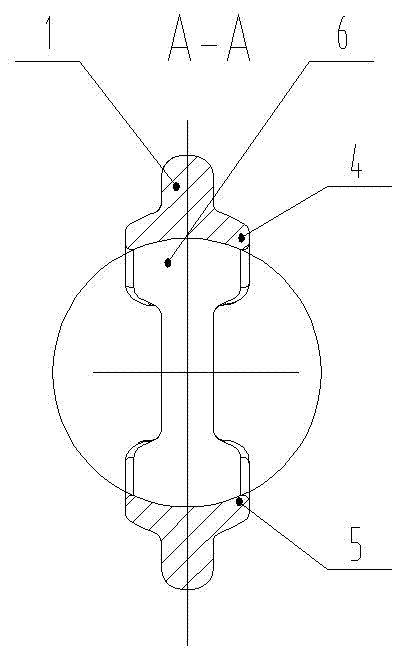
[0012] From Figure 1-Figure 3 It can be seen from the figure: a slewing bearing ball belt type positioning cage, which is characterized in that the slewing bearing ball belt positioning cage is mainly composed of a belt body 1, a ball seat hole 6, an upper arc-shaped boss 4 and a lower arc Shaped boss 5, the belt 1 is a long belt with a flat rectangular cross section, the upper and lower sides of the belt 1 are circular arc transitions, and the left end of the belt 1 is provided with a dovetail joint 2, and on the left end of the belt 1 The right end of the belt body 1 is correspondingly provided with a dovetail groove 3, and the dovetail joint 2 and the dovetail groove 3 are correspondingly embedded to form a complete circle, which is used as a cage body for each ball, and the length of the belt body 1 can be adjusted according to the slewing support roller. The circumference of the center of the track is intercepted, and the versatility is strong. The upper and lower parts ...


PUM


Abstract

The invention relates to a slewing bearing ball belt-type locating retainer and belongs to a slewing bearing. The retainer is characterized by consisting of a belt body, ball seat holes, upper circular-arc bosses and lower circular-arc bosses, wherein the belt body is a long belt of which the section is in a flat rectangle shape, the left end of the belt body is a provided with a dovetail-shaped joint, and the right end part of the belt body is correspondingly provided with a dovetail groove; the dovetail-shaped joint and the dovetail groove are subjected to corresponding scarf joint to form a whole circle serving as the retainer body of each ball; the upper part and lower part of the front surface and rear surface of the belt body are alternately respectively provided with the upper circular-arc boss and the lower circular-arc boss which are integrally molded together with the belt body from left to right by taking the center line of the length direction of the belt body as reference; and the belt body as well as each group of upper circular-arc bosses and each group of lower circular-arc bosses on the front surface and rear surface of the belt body are provided with spherical surface holes serving as the ball seat holes, and each ball seat hole is respectively slidably provided with a ball, therefore the performance of the slewing bearing performance is greatly improved, theservice life is long, and the application field is wide.

Description

technical field [0001] The invention belongs to slewing bearings, in particular to a positioning cage for slewing bearing balls. Background technique [0002] The existing four-point contact single row ball type slewing bearing, its rolling elements (balls) are usually isolated by spacer blocks, but the existing spacer blocks are prone to wear after long-term use, which increases the circumferential gap between the balls, and the slewing bearing rotates When the isolation block will make collision noise, or even dump and block the raceway, especially when the slewing bearing requires vertical installation, high speed, low starting torque, low noise and long life, the existing isolation block cannot meet these requirements , so that the scope of use of the slewing ring is limited. Contents of the invention [0003] The purpose of this invention is to propose a ball belt type positioning cage for slewing bearings, which is not only convenient and quick to install, but also ...

Claims


Application Information

Patent Timeline
Patent Type & Authority Patents(China)
IPC IPC(8): F16C33/38F16C33/44
Inventor 刘扬王春琦张文举黄鲁何东生
Owner MAANSHAN FY PRECISION MACHINERY CO LTD
Learn More