
Rotor blade for a wind turbine

A technology of rotor blades and wind energy equipment, which is applied to wind power generation, mechanical equipment, and wind turbines in the same direction as the wind to achieve the effect of reducing the angle of attack

Active Publication Date: 2019-02-05
WOBBEN PROPERTIES GMBH
View PDF19 Cites 0 Cited by
  • Summary
  • Abstract
  • Description
  • Claims
  • Application Information

AI Technical Summary

Problems solved by technology

However, simply stiffening the rotor blade leads to a significantly increased weight of the rotor blade

Method used


Image

  • Rotor blade for a wind turbine
  • Rotor blade for a wind turbine
  • Rotor blade for a wind turbine

Examples


Embodiment Construction

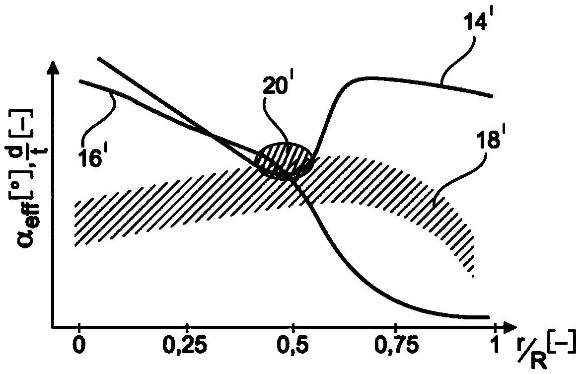
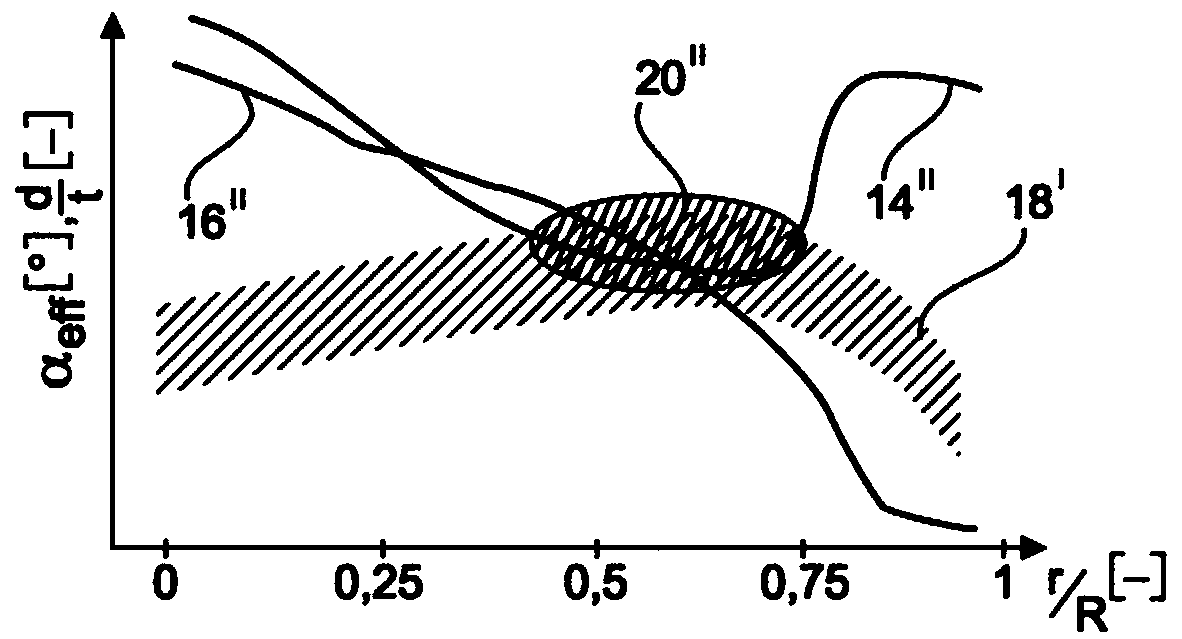
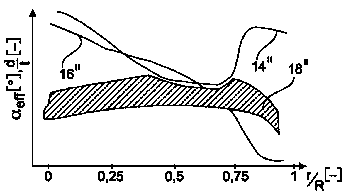
[0042] Figure 1a A diagram is shown in which the maximum permissible angle of attack 14', ie the stall angle, and the relative profile thickness 16' are schematically plotted as a function of their position r along the longitudinal axis of the blade. The position r is specified in a normalized manner by its relative radius r / R with respect to the outer radius R of the rotor, with values ​​from 0 to 1, which thus correspond to values ​​from 0% to 100%. Figure 1a The ratios are shown as usually exist in rotor blades according to the prior art. exist Figure 1a In the graph of , the stall angle 14' is plotted as the limiting angle 14' of a contaminated or wet rotor blade. The limit angle 14' can here be regarded as the maximum permissible effective angle of attack α of the rotor blades during operation of the wind turbine eff . additionally, in Figure 1a The graph 16' of the relative profile thickness d / t of a prior art rotor blade is shown.

[0043] The curve 14' of the...


PUM


Abstract

The invention relates to a rotor blade of an aerodynamic rotor of a wind turbine having a rotor rotation axis and an outer radius, comprising a blade root for attaching to a rotor hub, a blade tip oriented away from the blade root, a blade longitudinal axis running from the blade root to the blade tip, a blade leading edge that faces forward in a direction of motion of the rotor blade, a blade trailing edge that faces backward in a direction of motion of the rotor blade, and profile sections that change along the blade longitudinal axis, wherein each profile section has a chord that extends from the blade leading edge to the blade trailing edge, and each chord has an installation angle as an angle in relation to a rotor plane, wherein the installation angle first decreases from the blade root to the blade tip in a blade inner region oriented toward the blade root, then increases in a blade central region, and decreases again in a blade tip region oriented toward the blade tip. The invention also relates to a rotor for a wind turbine and to a corresponding wind turbine.

Description

technical field [0001] The invention relates to a rotor blade of a rotor of a wind energy installation. Furthermore, the invention relates to a corresponding rotor of a wind energy installation. In addition, the invention relates to a corresponding wind energy installation. Background technique [0002] Wind power plants are generally known and the most common type of wind power plant today is the so-called horizontal-axis wind power plant. In such a wind turbine, the rotor with rotor blades arranged essentially in a rotor plane rotates about an essentially horizontal axis of rotation. Usually, wind energy installations are designed for an average wind speed, the length or radius of the rotor blades and the average wind speed at the installation site of the wind energy installation being correlated with the power generated by the wind energy installation. [0003] Those skilled in the art refer to the position on the rotor blade on the longitudinal axis of the rotor blade...

Claims


Application Information

Patent Timeline
Patent Type & Authority Applications(China)
IPC IPC(8): F03D1/06
CPCF03D1/0633F05B2240/301F03D1/0641Y02E10/72
Inventor 拉尔夫·梅辛
Owner WOBBEN PROPERTIES GMBH
Learn More