Test bench for automobile climbing capacity and differential lock performance
A technology of climbing ability and differential lock, applied in vehicle testing, machine/structural component testing, machine gear/transmission mechanism testing, etc., can solve problems such as unfavorable roller maintenance, maintenance and timely replacement, and reduce maintenance. The effect of maintenance difficulty, reduction of manufacturing costs, ease of transportation and installation
- Summary
- Abstract
- Description
- Claims
- Application Information
AI Technical Summary
Problems solved by technology
Method used
Image
Examples
Embodiment 1
[0027] Embodiment 1: the approach angle of the tested car is 21°.
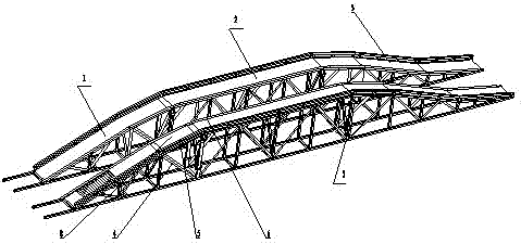
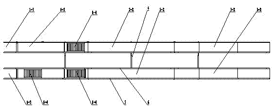
[0028] Adjust the connection position of the connecting sleeve 4 so that the distance between the centerline of the left and right bridge body is consistent with the wheel base of the vehicle being tested. The angle of inclination of the adjustable part of the uphill bridge body 1 is 21° through the approach bridge hinge mechanism, and the fixed base 1-12 is selected. Six (in order from left to right) connecting holes, connect the vertical support 1-6, the connecting seat 1-9 and the fixed base 1-12 through the bolt assembly, and then connect the uphill bridge body 1 through the bolt assembly The lower end of the adjustable part is connected with the third connecting hole of the fixed base 1-12. After the installation process is completed, the roller mechanism cover plate 8 can be put on to detect the climbing ability of the vehicle to be tested; the roller mechanism cover plate can be removed to test the perf...
Embodiment 2
[0029] Embodiment 2: the approach angle of the tested car is 19°.
[0030] Adjust the connecting position of the connecting sleeve 4 so that the distance between the centerline of the left and right bridge body is consistent with the wheelbase of the vehicle being tested. The inclination angle of the adjustable part of the uphill bridge body 1 is 19° through the approach bridge hinge mechanism, and the extended vertical support 1- 6. Select the fifth (from left to right) connection hole of the fixed base 1-12, connect the vertical support 1-6, the connecting base 1-9 and the fixed base 1-12 through the bolt assembly, and then The hook 1-10 of the extended plate is assembled with the hinged shaft 1-11 of the extended plate installed at the lower end of the approach bridge frame, and is connected with the third connecting hole on the fixed base 1-12 of the uphill bridge body through the inclined brace of the extended plate. The extension plate connection seat is connected with t...
Embodiment 3
[0031] Embodiment 3: the approach angle of the tested car is 16°.
[0032] Adjust the connecting position of the connecting sleeve 4 so that the distance between the centerline of the left and right bridge body is consistent with the wheelbase of the vehicle being tested. The inclination angle of the adjustable part of the uphill bridge body 1 is 16° through the approach bridge hinge mechanism, and the extended vertical support 1- 6. Select the fourth (from left to right) connecting hole of the fixed base 1-12, connect the vertical support 1-6, the connecting base 1-9 and the fixed base 1-12 through the bolt assembly, and then The hook 1-10 of the extended plate is assembled with the hinged shaft 1-11 of the extended plate mounted on the lower end of the approach bridge frame, and connected with the second connecting hole on the fixed base 1-12 of the uphill bridge body through the inclined brace of the extended plate. The extension plate connection seat is connected with the ...
PUM
 Abstract
Description
Claims
Application Information
 - R&D
- Intellectual Property
- Life Sciences
- Materials
- Tech Scout
- Unparalleled Data Quality
- Higher Quality Content
- 60% Fewer Hallucinations
Browse by: Latest US Patents, China's latest patents, Technical Efficacy Thesaurus, Application Domain, Technology Topic, Popular Technical Reports.
© 2025 PatSnap. All rights reserved.Legal|Privacy policy|Modern Slavery Act Transparency Statement|Sitemap|About US| Contact US: help@patsnap.com


