Travelling wave fault ranging method and device based on differential output of Rogowski coil

A traveling wave ranging device and traveling wave fault technology, applied in directions such as fault locations, can solve problems such as complex mathematical operations

Inactive Publication Date: 2012-01-04
SHANDONG UNIV
View PDF5 Cites 12 Cited by
  • Summary
  • Abstract
  • Description
  • Claims
  • Application Information

AI Technical Summary

Problems solved by technology

The former requires more complex mathematical operations; the latter requires the addition of analog circuits

Method used


Image

  • Travelling wave fault ranging method and device based on differential output of Rogowski coil
  • Travelling wave fault ranging method and device based on differential output of Rogowski coil
  • Travelling wave fault ranging method and device based on differential output of Rogowski coil

Examples


Embodiment Construction

[0074] Specific embodiments of the present invention will be further described below in conjunction with the accompanying drawings.

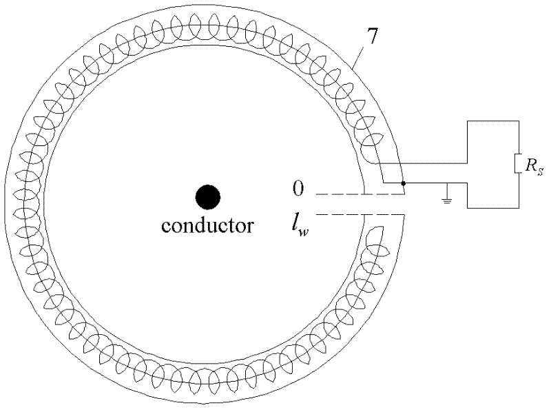
[0075] attached figure 1 A schematic diagram of the structure of a Rogowski coil is shown. The Rogowski coil was invented by the Russian scientist Rogowski in 1912. It is made of enameled wire evenly wound on the ring frame, and the conductor of the primary current passes through the center of the circular frame. The cross-section of the skeleton is usually circular or rectangular, and the material of the skeleton is usually non-ferromagnetic materials such as plastic or ceramics. Its relative magnetic permeability is the same as that in air, and the primary current will flow along the direction of the circular skeleton. A closed magnetic field is generated, and when the current changes, the coil wound on the skeleton will generate an induced voltage. R in the figure S is the sampling resistor.

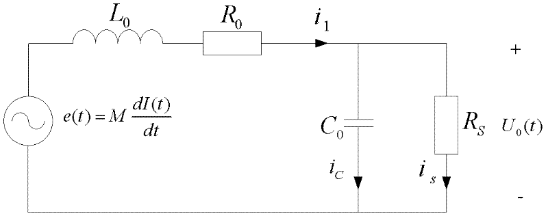
[0076] attached figure 2 is the equivalent ...


PUM


Abstract

The invention relates to a travelling wave fault ranging method and a travelling wave fault ranging device based on the differential output of a Rogowski coil, and belongs to the field of relay protection of electric power systems. The conventional travelling wave ranging method has congenitally deficient reliability and accuracy due to the constraint of the bandwidth of an electromagnetic current transformer (CT). A sensing head, namely the Rogowski coil of an electronic current transformer (ECT) has the advantages of simple structure, wide frequency band, high linearity, high response speed and the like, and is extremely suitable for transmitting travelling wave signals. An output signal of the Rogowski coil is the differential coefficient of primary current, amplitude variations at discontinuity points are extremely obvious, and the detection of a travelling wave head is further facilitated. The invention provides a new method for positioning faults by directly using current travelling wave differential signals (named differential travelling waves in the invention) output by the Rogowski coil. By the method, the problem of positioning of travelling wave faults in a digital (intelligent) electric substation is solved.

Description

technical field [0001] The invention relates to a traveling wave fault ranging method and device based on Rogowski coil differential output, and belongs to the field of electric power system relay protection. technical background [0002] In recent years, digital substation technology has developed rapidly in my country, and is at the forefront of the world in terms of engineering and practicality. There have been nearly 300 digital substations of different voltage levels that have been reconstructed, piloted or newly built across the country. One of the outstanding signs of digital substation is the adoption of electronic transformers. The most widely used electronic current transformers are Rogowski current transformers. Compared with traditional electromagnetic transformers, electronic transformers have small size and light weight. , wide frequency range, large dynamic range, low insulation requirements, no magnetic saturation, no ferromagnetic resonance, digital output ...

Claims


Application Information

Patent Timeline
Patent Type & Authority Applications(China)
IPC IPC(8): G01R31/08
Inventor 高厚磊向珉江邹贵彬朱国防安艳秋王慧
Owner SHANDONG UNIV
Why Eureka
Try Eureka