Bogie for track-guided vehicle

A bogie and vehicle technology, applied in the field of rail-based vehicles, can solve the problems of partial wear and large space of the tires of the road wheels 57, and achieve the effect of preventing partial wear

Active Publication Date: 2012-01-04
三菱重工工程株式会社
View PDF8 Cites 28 Cited by
  • Summary
  • Abstract
  • Description
  • Claims
  • Application Information

AI Technical Summary

Problems solved by technology

That is, when the actuator 64 carries out the same control under the situation of any turn left and right, the steering angle of the road wheel 57 positioned at the inside of the curve portion and the steering angle of the road wheel 57 positioned at the outside become different when turning right and turning left. The same, as a result, the tires of the road wheels 57, etc., may be partially worn
[0013] ...

Method used


Image

  • Bogie for track-guided vehicle
  • Bogie for track-guided vehicle
  • Bogie for track-guided vehicle

Examples


no. 1 example

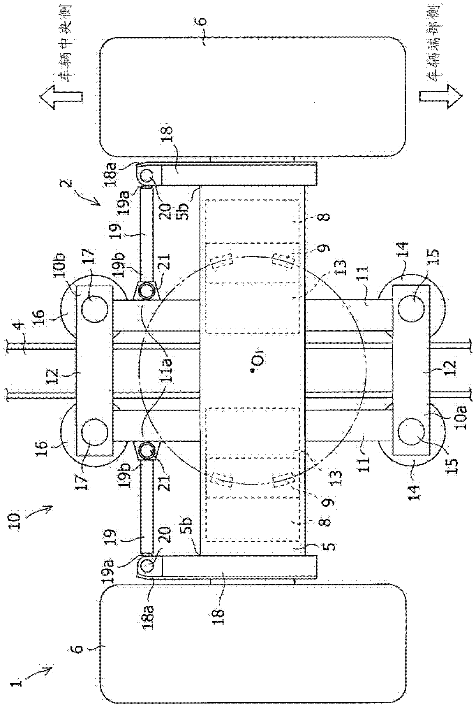
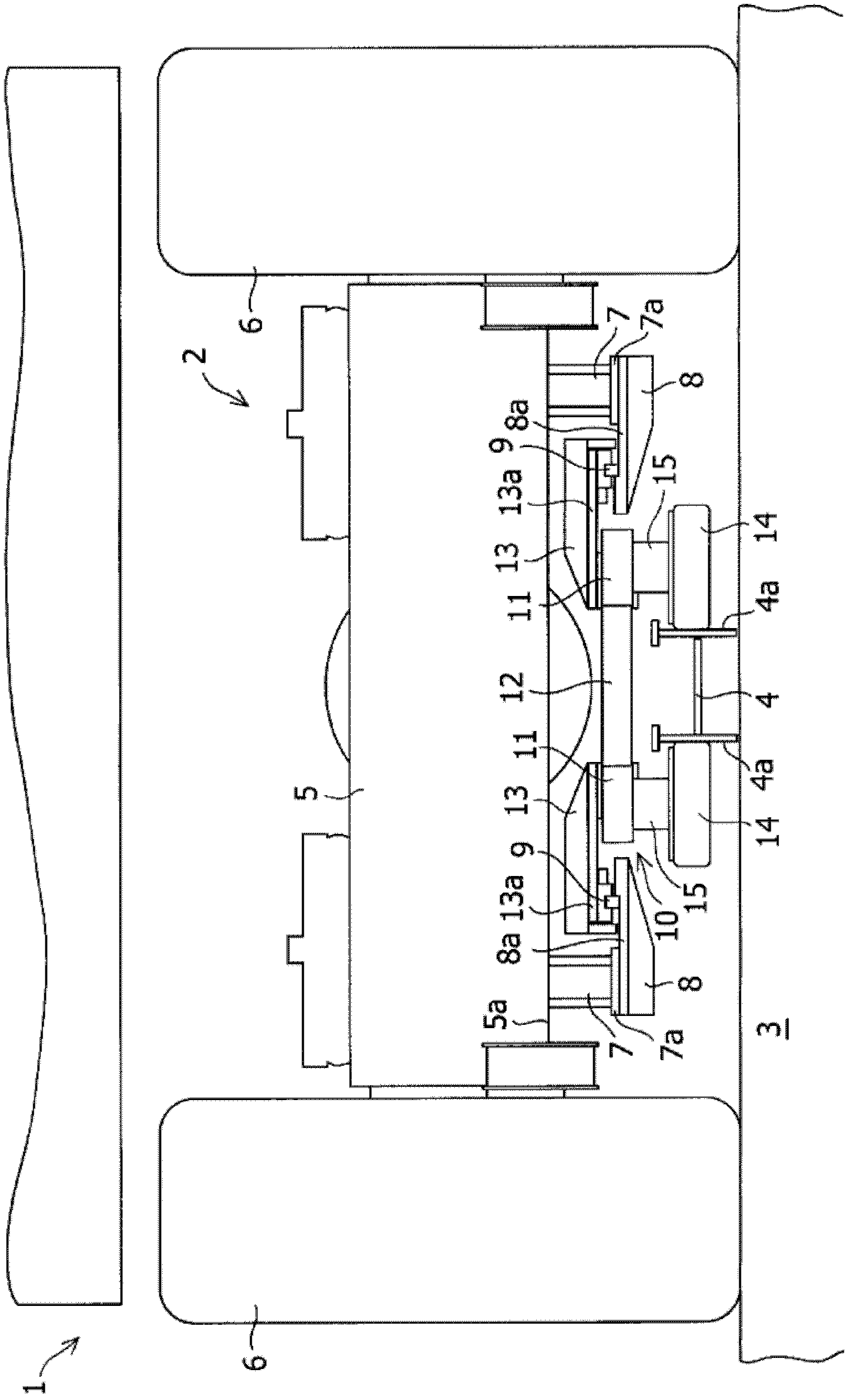
[0042] Below, while referring to the attached Figure 1 Next, a bogie for a railway vehicle according to a first embodiment of the present invention will be described. figure 1 It is a top view of the front side bogie in the vehicle front and rear direction of the rail-based vehicle in the first embodiment of the present invention, figure 2 Viewed from the vehicle end side figure 1 Front view of the bogie.

[0043] Such as figure 1 and figure 2 As shown, a vehicle 1 is provided with bogies 2 respectively at front and rear parts (rear parts not shown) in the vehicle front and rear direction, and runs on predetermined rails 3 . A guide rail 4 having an H-shaped cross-section is laid on a substantially central portion of the rail 3 in the vehicle width direction.

[0044] Such as figure 1 and figure 2 As shown, the bogie 2 is provided with an axle 5 extending in the vehicle width direction, and a pair of running wheels 6 are operablely attached to both ends of the a...

no. 2 example

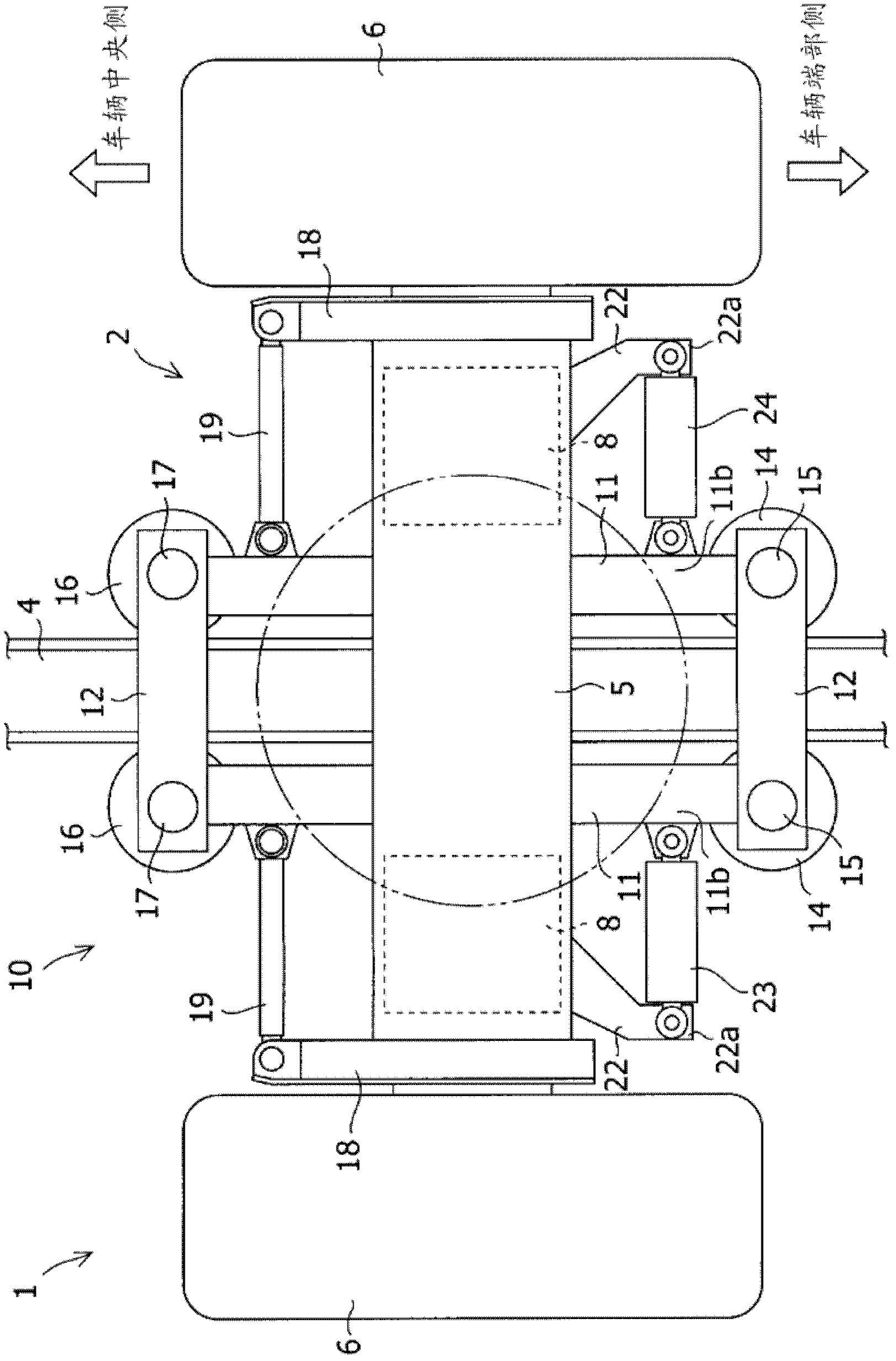
[0054] Below, while referring to the attached Figure 1 Next, a bogie for a railway vehicle according to a second embodiment of the present invention will be described. image 3 It is a plan view of the front side bogie in the vehicle front-rear direction of the rail-based vehicle according to the second embodiment of the present invention. The same symbols are assigned to the same parts as those described in the above-mentioned embodiments, and repeated descriptions are omitted.

[0055] Such as image 3As shown, in this embodiment, a pair of arms 22 formed to extend toward the vehicle end side are provided on each frame 8 of the axle 5 . The end portion 22a of the right arm 22 on the vehicle end side is connected to the vehicle end side portion 11b of the vertical frame 11 of the guide frame 10 with respect to the traveling direction of the vehicle by a rotary damper 23 extending in the vehicle width direction. When the vehicle 1 passes through a curved portion (not shown...

no. 3 example

[0060] Below, while referring to the attached Figure 1 Next, a bogie for rail-based vehicles according to a third embodiment of the present invention will be described. Figure 4 It is a plan view of the front bogie in the vehicle front and rear direction of the rail-based vehicle according to the third embodiment of the present invention. The same symbols are assigned to the same parts as those described in the above-mentioned embodiments, and repeated descriptions are omitted.

[0061] Such as Figure 4 As shown, the present embodiment puts the central axis O of the axle shaft 5 2 Relative to guide frame center O 1 (the center of rotation of the guide frame) is arranged offset on the vehicle center side in the vehicle front-rear direction. Although not shown, the bogie on the rear side of the vehicle 1 of this embodiment has the same structure as that of the above-mentioned embodiment.

[0062] Next, the force acting on the bogie when the bogie for a railway vehicle of...


PUM


Abstract

A bogie (2) for a track-guided vehicle (1) traveling on a predetermined track (3). The bogie (2) is provided with an axle (5) to which steerable travel wheels (6) are mounted, a guide frame (10) provided below the axle (5), a first pair of guide wheels (14) rotatably mounted to a vehicle end section-side end portion (10a) of the guide frame (10), a second pair of guide wheels (16) rotatably mounted to a vehicle center-side portion (10b) of the guide frame (10), a pair of tie rod arms (18) mounted to the axle (5) and formed so as to extend from the axle (5) toward the vehicle center side, and a pair of tie rods (19), each tie rod (19) interconnecting the guide frame (10) and each of the pair of tie rod arms (18).

Description

technical field [0001] The present invention relates to a track-based vehicle that runs on a predetermined track, and specifically relates to a track-based vehicle bogie that is guided and manipulated by guide rails provided on the track. Background technique [0002] Conventionally (for example, Patent Document 1 and Patent Document 2), there have been proposed bogies for track-based vehicles that run along guide rails provided on a track by providing a steering mechanism using guide wheels. [0003] Figure 10 An example of a conventional rail-based vehicle bogie is shown, and a plan view of a front-side bogie in the vehicle front-rear direction of the rail-based vehicle is shown. [0004] Such as Figure 10 As shown, a bogie 52 of a rail-based vehicle 51 travels along guide rails 53 provided on a rail, and is provided with a guide frame 54 formed in a rectangular shape in plan view. A pair of guide wheels 55 are rotatably attached to the vehicle end side portion 54a of t...

Claims


Application Information

Patent Timeline
IPC IPC(8): B61F5/38B61B13/00
CPCB61B10/04B61B13/06B61F5/38
Inventor 仓桥大树藤尾宣幸河野浩幸矢延雪秀川内章央片平耕介
Owner 三菱重工工程株式会社
Why Eureka
Try Eureka