Check patentability & draft patents in minutes with Patsnap Eureka AI!

Thermal treatment furnace

A technology for heat treatment furnaces and furnace shells, applied in heat treatment furnaces, heat treatment equipment, furnaces, etc., can solve the problems of unavailable heat treatment equipment, high labor intensity, and easy burnout of crawler heaters, etc., to improve heat treatment efficiency, The effect of solving cost waste

Inactive Publication Date: 2013-09-25
CHINA INTERNATIONAL MARINE CONTAINERS (GROUP) CO LTD
View PDF9 Cites 0 Cited by
  • Summary
  • Abstract
  • Description
  • Claims
  • Application Information

AI Technical Summary

Problems solved by technology

At present, there is no equipment suitable for the heat treatment of the above products in the market
In addition, the large-scale heat treatment furnace equipment is not suitable for local heat treatment such as the joint weld between the pipe and the tube plate, the girth weld between the tube plate and the cylinder, and the U-shaped pipe bend section. The existing heat treatment method uses crawler heaters and insulation cotton It is fixed on the part that needs heat treatment, which not only affects the production efficiency, but also has high labor intensity, and the crawler heater used for local heat treatment is easy to burn out

Method used


Image

  • Thermal treatment furnace
  • Thermal treatment furnace
  • Thermal treatment furnace

Examples


Embodiment Construction

[0033] In the following, the present invention will be specifically described through exemplary embodiments. It is to be understood, however, that elements, structures and characteristics of one embodiment may be beneficially incorporated in other embodiments without further recitation.

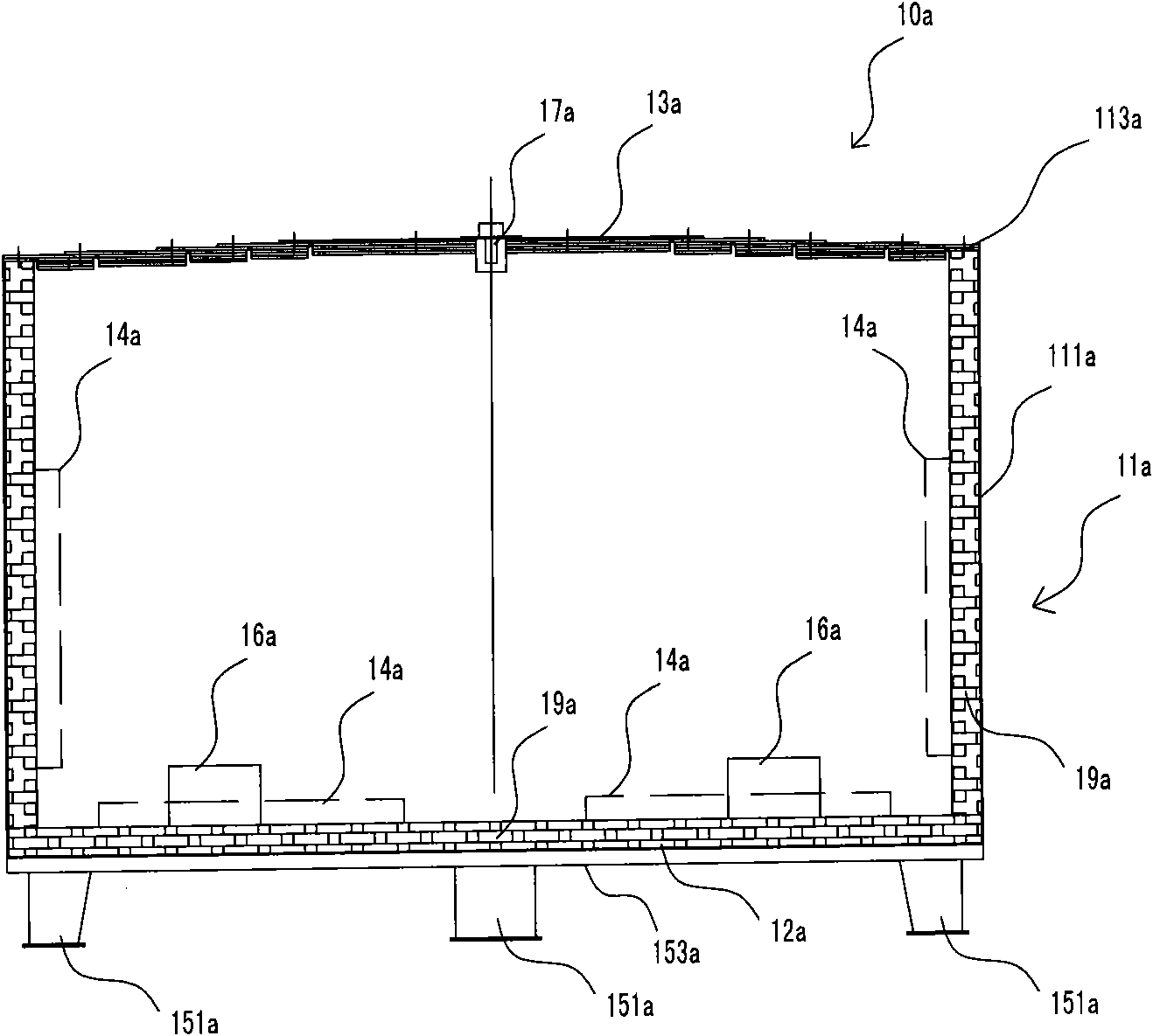
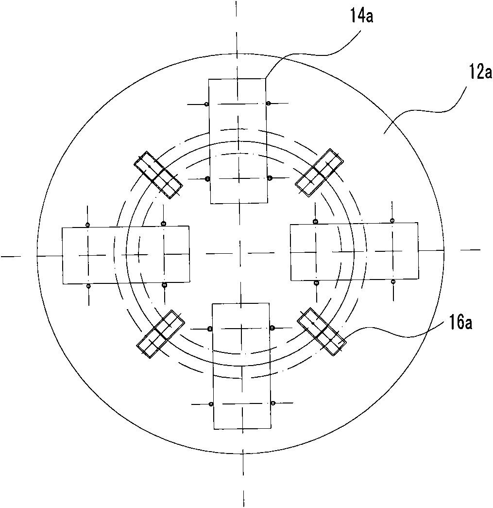
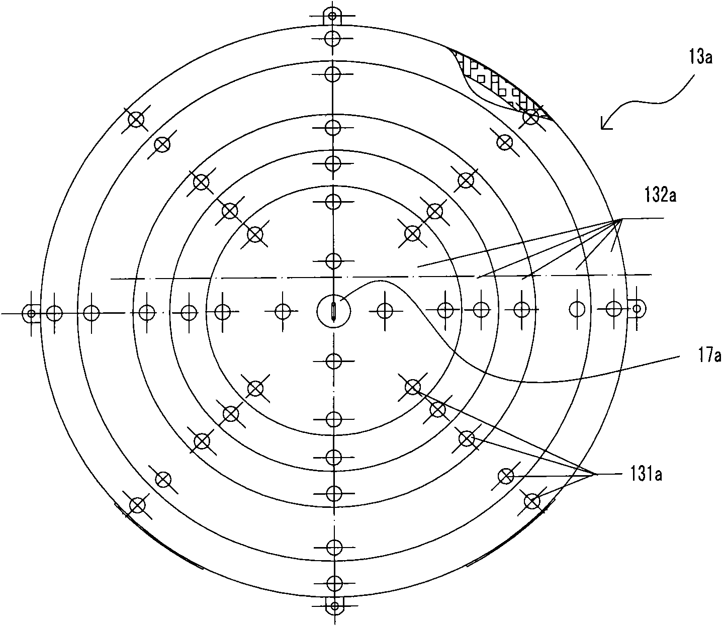
[0034] figure 1 Shown is a heat treatment furnace 10a according to an embodiment of the present invention, comprising an outer shell 11a, a bottom plate 12a, a furnace cover 13a and at least one heater 14a. Wherein, the bottom plate 12a is arranged at the bottom of the casing 11a, and the furnace cover 13a is arranged at the top of the casing 11a. In order to heat the workpiece to be processed, preferably, there are multiple heaters 14a installed on the inner wall of the casing 11a and / or the bottom plate 12a respectively. In order to play the role of fixed support, the heat treatment furnace 10a of the present invention also includes at least one fixed furnace base 151a and at least one mo...


PUM

PropertyMeasurementUnit
lengthaaaaaaaaaa

Abstract

The invention discloses a thermal treatment furnace, which comprises a shell, a bottom plate, a furnace lid, at least one heater, at least one fixed furnace seat and at least one movable support, wherein the bottom plate is arranged at the bottom part of the shell; the furnace lid is arranged at the top part of the shell; the heaters are arranged on the inner wall of the shell and / or the bottom plate; the fixed furnace seats are arranged on the outer wall of the bottom plate; and the movable supports are arranged on the outer wall of the shell. According to the thermal treatment furnace disclosed by the invention, various thermal treatment requirements of small and medium sized pressure containers or parts with various forms can be met.

Description

technical field [0001] The invention relates to a heat treatment equipment, in particular to a heat treatment furnace. Background technique [0002] With the enlargement of pressure vessels, in order to meet the needs of the overall heat treatment of pressure vessels, many heavy pressure vessel manufacturers have built large fuel heat treatment furnaces. However, these large-scale furnaces can only meet the needs of large-scale pressure vessels, and the utilization rate is relatively low. At the same time, some parts of large-scale pressure vessels also need to undergo intermediate heat treatment or post-weld heat treatment during the manufacturing process, which are not suitable for large-scale furnaces. heat treated. For small and medium-sized containers, due to economic reasons, material types, process specifications and production schedules, it is not suitable for separate or combined furnace heat treatment in large furnaces. At present, the equipment suitable for the ...

Claims


Application Information

Patent Timeline
Patent Type & Authority Patents(China)
IPC IPC(8): C21D9/00
Inventor 丛轶葛树涛曲萍王永斌
Owner CHINA INTERNATIONAL MARINE CONTAINERS (GROUP) CO LTD
Features
  • R&D
  • Intellectual Property
  • Life Sciences
  • Materials
  • Tech Scout
  • Unparalleled Data Quality
  • Higher Quality Content
  • 60% Fewer Hallucinations
Learn More