Excavator converging control system and excavator thereof

A technology for control systems and excavators, applied to mechanically driven excavators/dredgers, fluid pressure actuated system components, mechanical equipment, etc., can solve problems such as low operating efficiency, unsmooth operation, and poor operating comfort, and achieve The effect of improving work efficiency and operating comfort

Inactive Publication Date: 2012-01-11
BEIQI FOTON MOTOR CO LTD
View PDF5 Cites 13 Cited by
  • Summary
  • Abstract
  • Description
  • Claims
  • Application Information

AI Technical Summary

Problems solved by technology

However, due to the preset parameters of the hydraulic system and transmission system of the excavator, and the variability of the flow rate of the hydraulic oil output by various valves in the system under different pressures, the dynamic The rising speed of the arm or the action speed of the stick is too fast, which is not coordinated with the speed of other parts
When the boom or stick is combined with other components, the operation is not smooth, resulting in low operating efficiency and poor operating comfort
[0004] Therefore, in the case of confluence of booms or sticks in the prior art, the rising speed of the boom or the movement speed of the stick is too fast, which is not coordinated with the movement speed of other components, resulting in unsmooth operation, low operating efficiency of the excavator, and poor operating comfort

Method used


Image

  • Excavator converging control system and excavator thereof
  • Excavator converging control system and excavator thereof
  • Excavator converging control system and excavator thereof

Examples


Embodiment Construction

[0026] In order to make the purpose, technical solutions and advantages of the present invention clearer, the technical solutions of the present invention will be clearly and completely described below in conjunction with the embodiments and accompanying drawings. Apparently, the described embodiments are part of the embodiments of the present invention, rather than Full examples. Based on the embodiments of the present invention, all other embodiments obtained by persons of ordinary skill in the art without creative efforts fall within the protection scope of the present invention.

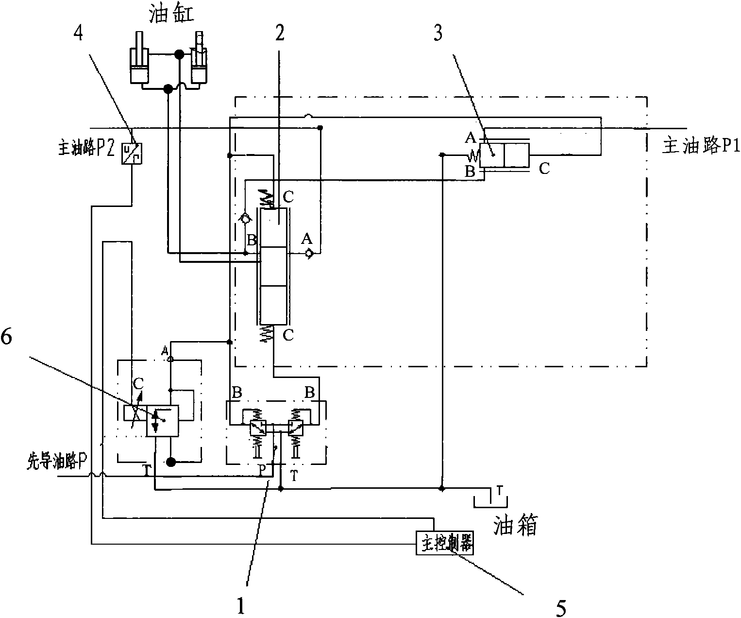
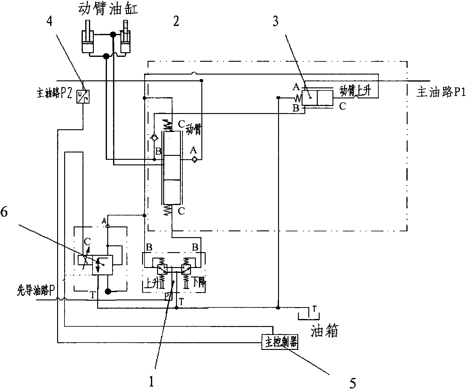
[0027] see figure 1 , The confluence control system for an excavator provided by an embodiment of the present invention includes: a pilot valve 1 , a main valve 2 , a confluence valve 3 , a pressure sensor 4 , a main controller 5 and a proportional pressure reducing valve 6 .

[0028] Among them, the pilot valve 1 is a manual mechanical valve. The pilot valve 1 is connected to the pressure sourc...


PUM


Abstract

The invention discloses an excavator converging control system and an excavator thereof. The system comprises a pilot valve, a main valve and a converging valve, wherein the control end of the main valve is connected with the control end of the converging valve, and the output end of the pilot valve is respectively connected with the control ends of the main valve and the converging valve; a pressure sensor is connected with the control end of the main valve to detect the pressure value of the input end of the main valve and send the pressure value to a main controller; the main controller is connected with the pressure sensor and the control end of a proportional pressure reducing valve, acquires the operation state of the excavator according to the pressure value, and adjusts the opening of the proportional pressure reducing valve according to the speed of a movable arm or a bucket rod which corresponds to the preset operation state; and the input end of the proportional pressure reducing valve is respectively connected to an oil line between the output end of the pilot valve and the control end of the main valve as well as between the output end of the pilot valve and the control end of the converging valve, and the proportional pressure reducing valve is used for shunting the hydraulic oil which is output to the main valve and the merging valve by the pilot vavle under the control of the main controller. The action speed of the movable arm or the bucket rod of the excavator is coordinated with that of the other parts, so the working efficiency and the operation comfortability of the excavator are improved.

Description

technical field [0001] The invention relates to an excavator merging control technology, in particular to an excavator merging control system and an excavator thereof. Background technique [0002] At present, the lifting of the boom of the excavator is driven and controlled by the hydraulic system and the transmission system. In order to meet the needs of accelerating the lifting speed of the boom, the excavator supplies oil to the boom at the same time in the way of confluence of two pumps. Similarly, the digging and unloading actions of the excavator stick also supply oil to the stick at the same time in the way of double pump confluence. [0003] The existing excavator hydraulic system and transmission system, for the boom movement part, includes: the pilot valve that controls the boom to move up or down, the main valve that controls the boom’s rising or falling speed, and the main valve to jointly control the boom. Combiner valve for rising speed. For the stick moveme...

Claims


Application Information

Patent Timeline
Patent Type & Authority Applications(China)
IPC IPC(8): E02F3/43F15B11/02F15B21/08
Inventor 陈宗宜陈明李靖张琨蔡文远王可峰张博友胡学军张军荣李兵
Owner BEIQI FOTON MOTOR CO LTD
Why Eureka
Try Eureka