Range sensing apparatus

A technology of sensing device and range, applied in the direction of measuring device, measuring device casing, transmission device control, etc., can solve the problems of increasing manufacturing cost, increasing the number of parts, complex process and so on

Inactive Publication Date: 2012-01-11
DENSO CORP +1
View PDF7 Cites 0 Cited by
  • Summary
  • Abstract
  • Description
  • Claims
  • Application Information

AI Technical Summary

Problems solved by technology

However, this will result in an increased part count as well as increased processing costs
[0007] In the case of Japanese Unexamined Patent Publication No. 2006-118643A (corresponding to US2006 / 0093169A1), when a large amount of hydraulic fluid and foreign matter move downward, it may cause sliding failure of the slider
Also, adequate and effective removal of foreign matter cannot be achieved unless holes of sufficiently large size are provided for the removal of foreign matter
In addition, in the case of forming a plurality of holes in the rail, a complicated process will be required, which will disadvantageously increase the manufacturing cost

Method used


Image

  • Range sensing apparatus
  • Range sensing apparatus
  • Range sensing apparatus

Examples


no. 1 example

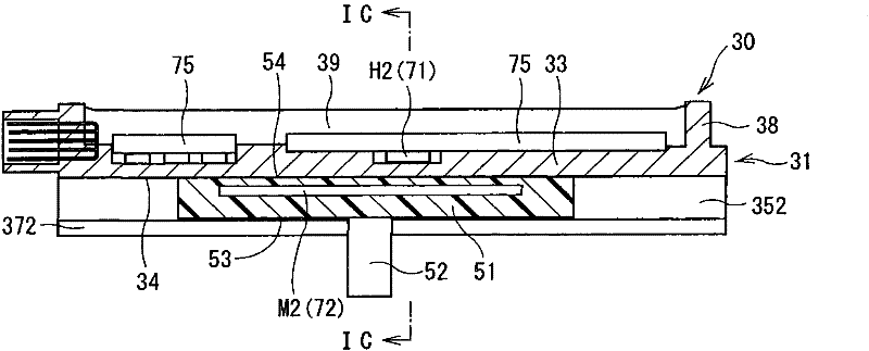
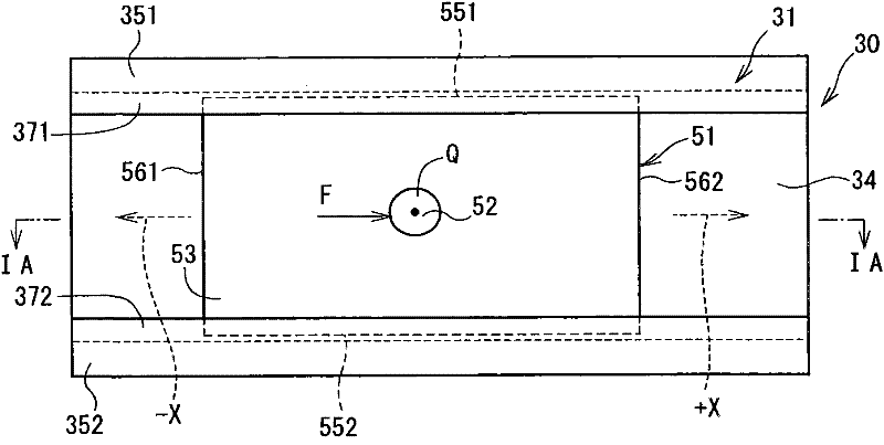
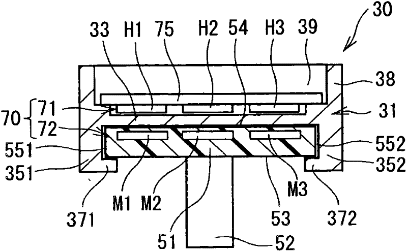
[0036] Figure 1A to Figure 10 A range sensing device according to a first embodiment of the invention is shown.

[0037] The range sensing device of the present embodiment is applied to an automatic transmission of a vehicle such as an automobile. Such as figure 2 As shown, the automatic transmission 2 includes a gearbox 3 , an oil pan 4 , a hydraulic pressure control device 20 , a braking mechanism 10 and a range sensing device 30 .

[0038] The gearbox 3 accommodates a plurality of friction elements that are engaged or disengaged from each other depending on the hydraulic pressure supplied from the hydraulic pressure control device 20 . The shift range of the automatic transmission changes according to the combination of engagement and disengagement of the respective friction elements. In the present embodiment, the shift range of the automatic transmission is changed among P-range, R-range, N-range and D-range. The P-range represents the parking range, while the R-ran...

no. 2 example

[0069] Next, we will refer to Figure 11 to Figure 12D A second embodiment of the present invention is described. The second embodiment differs from the first embodiment in the configuration of the casing 31 . In the following description, components similar to those of the first embodiment will be designated by the same reference numerals and will not be further described.

[0070] In the second embodiment, notches (recesses) 391, 392, 393, 394 are provided in the guide rails 371, 372 at the end portions of the movable range of the slider 51 so as to provide a gap between the movable range of the slider 51 and the housing. 31 external communication (communicate) (see Figure 11 ). In other words, each of the two opposing end surfaces (rail end surfaces) 395 , 396 , 397 , 398 of each rail 371 , 372 is separated from the adjacent end surface of the corresponding side plate 351 , 352 . The end surfaces 351a, 351b, 352a, 352b are recessed axially inwardly. in such as Figur...

no. 3 example

[0074] Next, we will refer to Figure 13A to Figure 16 A third embodiment of the present invention is described. In the third embodiment, the position sensor (displacement sensing means) is different from that of the first embodiment. Except for the position sensor, the rest of the structure of the range sensing device of the third embodiment is basically the same as that of the first embodiment. In the third embodiment, in Figure 15 A position sensor 80 shown in and used as a displacement sensing device includes a stationary sensor 81 and a movable sensor 82 . The stationary sensor 81 includes electrode plates, and the movable sensor 82 includes terminals each having contacts contacting a corresponding one of the electrode plates of the stationary sensor 81 . Thus, displacement of the slider 51 can be sensed by contact between the stationary sensor 81 and the movable sensor 82 . That is, the position sensor 80 is a contact type sensor (contact type displacement sensing m...


PUM


Abstract

The present invention relates to a range sensing apparatus. A housing (31,41) slidably guides a slider (51,61), which is driven in response to selection of a shift range of an automatic transmission. Upper and lateral sides of a movable range of the slider (51,61) are covered with the housing (31,41) . Thereby, application of hydraulic fluid and foreign objects to guide rails (371,372,471, 472)is limited to limit malfunction of the slider (51,61). Furthermore, even when the hydraulic fluid and foreign objects adhere to the guide rails (371,372,471, 472), the hydraulic fluid and foreign objects can be collected at ends of the movable range of the slider (51,61) and can be expelled to an outside of the housing (31,41)through open ends (381,382)of the housing (31,41).

Description

technical field [0001] The present invention relates to a range sensing device for an automatic transmission. Background technique [0002] There are known range sensing devices that sense the shift range of an automatic transmission. For example, in the range sensing device described in Japanese Unexamined Patent Publication No. 2002-175744A or Japanese Unexamined Patent Publication No. 2006-118643A (corresponding to US2006 / 0093169A1), using a sensor provided in a housing, based on The shifting range of the automatic transmission is sensed by the movement position (operated position) of the slider driven to reciprocate along the guide rail of the housing in response to selection of the shifting range. [0003] The range sensing device described in Japanese Unexamined Patent Publication No. 2002-175744A or Japanese Unexamined Patent Publication No. 2006-118643A (corresponding to US2006 / 0093169A1) is placed in a transmission in which the automatic transmission is injected. ...

Claims


Application Information

Patent Timeline
Patent Type & Authority Applications(China)
IPC IPC(8): F16H59/08F16H63/42
CPCF16H59/105G01D11/24F16H59/70G01D5/2497Y10T74/19251Y10T74/20018
Inventor 高木章金房巳贵男平川茂树木村隆浩三谷明弘永井祥太郎末繁惠一郎川野刚范
Owner DENSO CORP
Why Eureka
Try Eureka