Variable capacitor

A capacitor and variable technology, applied in the direction of variable capacitors, capacitors, capacitors that change the effective area of ​​electrodes, etc., can solve the problems of high processing cost, affecting electrical conductivity, and increasing the cost of variable capacitors.

Inactive Publication Date: 2004-09-01
MURATA MFG CO LTD
View PDF1 Cites 0 Cited by
  • Summary
  • Abstract
  • Description
  • Claims
  • Application Information

AI Technical Summary

Problems solved by technology

If the surface treatment is carried out on the whole surface of the cover 4, such as figure 2 As shown, when performing soldering, the solder S will rise into the inside of the cover 4 along the contact portion between the cover joint 18 of the cover 4 and the fixed piece 2 due to capillary phenomenon, and the moving piece 3 will be fixed by the solder S, and the flux will flow Intrude into the contact part of the cover 4 and the gasket 19 or the contact part of the gasket 19 and the moving piece 3, thus affecting the electrical conductivity
[0012] However, if only part of the surface of the cover 4 is surface treated, the processing cost is very high, thereby increasing the cost of the variable capacitor
In addition, it is not necessarily possible to prevent the penetration of the solder S into the inside of the cover 4 by merely surface treatment.

Method used


Image

  • Variable capacitor
  • Variable capacitor
  • Variable capacitor

Examples


Embodiment Construction

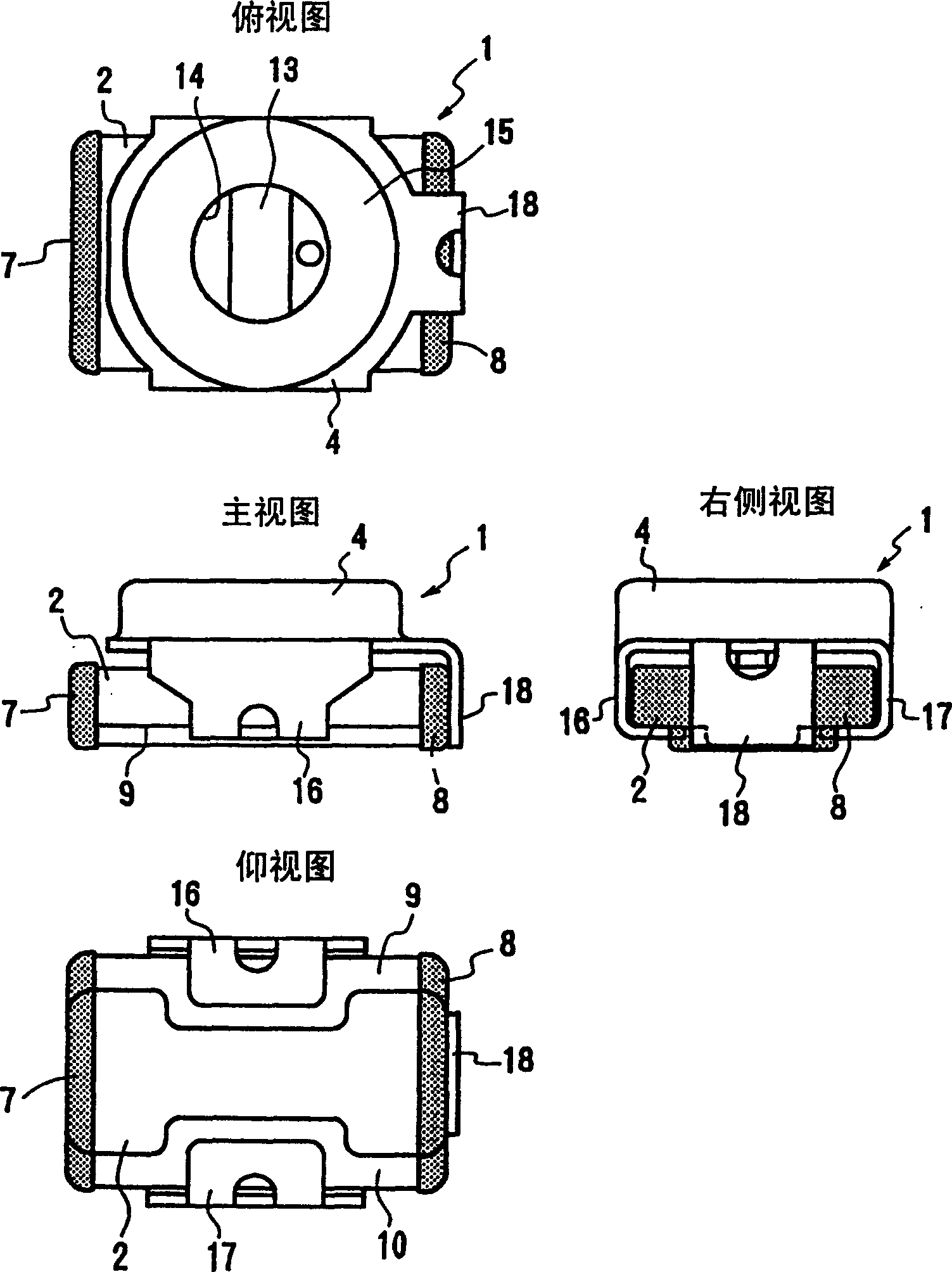
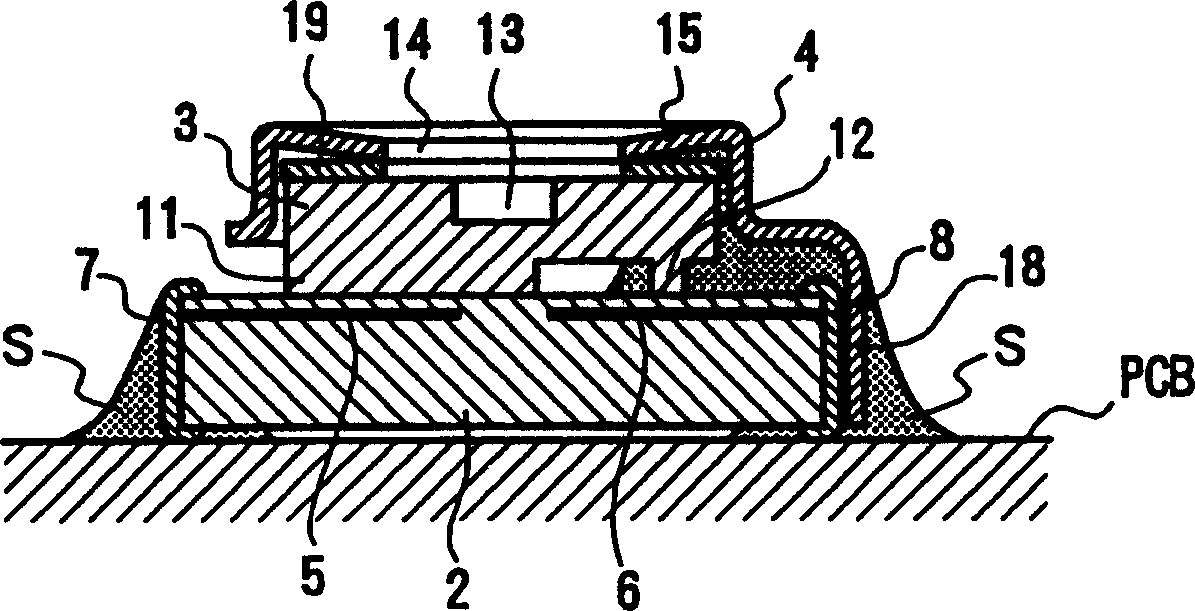
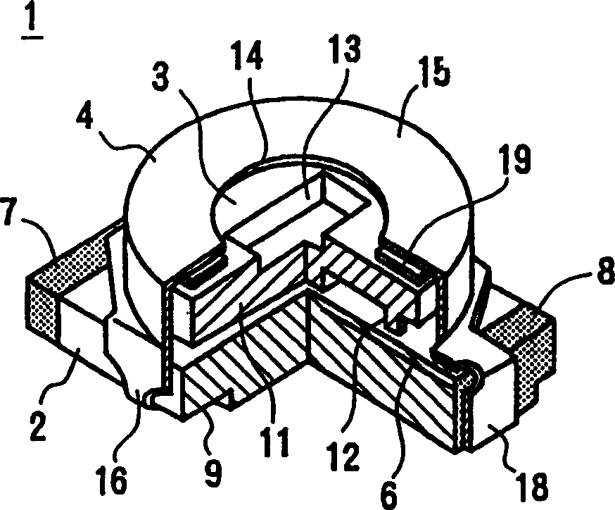
[0036] Figure 4 and Figure 5 Embodiment 1 of the variable capacitor 1' of the present invention is shown. The basic structure and reference of this embodiment figure 1 and figure 2 The variable capacitor 1 described is the same, and the same parts as the variable capacitor 1 are also denoted by the same symbols, so repeated description is omitted.

[0037] The cover 4 is made of spring-elastic conductive metal such as stainless steel or phosphor bronze. The entire surface of the cover 4 is surface treated (for example, gold-plated, silver-plated, tin-plated) to reduce contact resistance and improve solder wetting and adsorption performance. It is desirable that the surface is tinned as a whole.

[0038] On the way of the lid joint 18 integrally formed with the lid 4 , an outwardly expanding expansion protrusion 18 a is formed, and a liquid storage portion 20 is formed between the expansion protrusion 18 a and the stator 2 . The expansion protrusion 18 a in this examp...


PUM


Abstract

The invention provides a variable capacitor where solder can be surely prevented from infiltrating into the inside of a cover by improving a shape of the cover. This variable capacitor is provided with a stator 2, having stator electrodes 5, 6 and stator terminals 7, 8 which are electrically connected with the stator electrodes, a rotor 3 which is arranged on the upper part of the stator 2 and is provided with a rotor electrode 11 facing the stator electrodes 5, 6 via dielectrics, and a conductive cover 4 having a cover terminal 18 for external connection which is electrically connected with the rotor electrode 11, fixed to the stator 2 so as to hold the rotor 3 rotatably to the stator 2 and stretched along a side surface of the stator 2 as far as the vicinity of a lower surface position of the stator 2. A protruded part 18a for reserve is formed in the middle part of the cover terminal 18, so that solder and flux S are prevented from infiltrating into the inside of the cover 4, when reflow soldering is performed.

Description

technical field [0001] The present invention relates to a variable capacitor, in particular to a chip-type variable capacitor whose electrostatic capacity is changed by rotating a movable piece relative to a fixed piece. Background technique [0002] This variable capacitor is described in JP-A-11-260666. Figure 1 ~ Figure 3 The variable capacitor 1 described in this publication is shown. [0003] The variable capacitor 1 generally consists of a fixed piece 2 , a moving piece 3 and a cover 4 . [0004] The main part of the stator 2 is composed of ceramic dielectric and is in the shape of a rectangular plate. Stator electrodes 5 and 6 having bilaterally symmetrical shapes are formed inside the stator 2 in the vicinity of the surface layer. Stator joints 7 and 8 made of conductive films are formed on the outer surfaces of both ends along the length direction of the stator 2 and are electrically connected to the stator electrodes 5 and 6 . In addition, the shapes of the two...

Claims


Application Information

Patent Timeline
Patent Type & Authority Patents(China)
IPC IPC(8): H01G5/00H01G5/06H01G5/08
CPCH01G5/014H01G5/06
Inventor 柴田泰伸
Owner MURATA MFG CO LTD
Why Eureka
Try Eureka