Damper device

A shock absorber and input component technology, applied in the direction of spring/shock absorber, shock absorber, power device, etc.

Pending Publication Date: 2021-12-17
AISIN AW INDUSTRIES CO LTD
View PDF8 Cites 0 Cited by
  • Summary
  • Abstract
  • Description
  • Claims
  • Application Information

AI Technical Summary

Problems solved by technology

Therefore, for the above-mentioned shock absorber device, there is still room for improvement in terms of assemblability and maintainability.

Method used


Image

  • Damper device
  • Damper device
  • Damper device

Examples


Embodiment Construction

[0016] Next, an embodiment for implementing the invention of the present disclosure will be described with reference to the drawings.

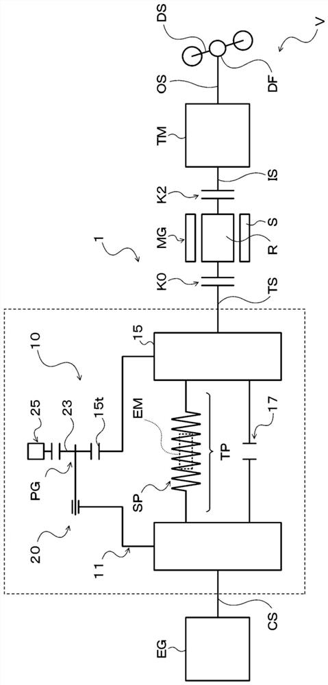
[0017] figure 1 It is a schematic configuration diagram showing the power transmission device 1 including the damper device 10 according to the first embodiment of the present invention. The power transmission device 1 shown in the same figure is mounted on a vehicle V including an engine (internal combustion engine) EG that generates power by explosively combusting a mixture of hydrocarbon fuel such as gasoline, light oil, or LPG, and air. The part that transmits the power of EG to the drive shaft DS. Such as figure 1 As shown, the power transmission device 1 includes, in addition to the shock absorber device 10 connected to the crankshaft CS of the engine EG, a motor generator MG, a transmission TM, and a motor arranged between the shock absorber device 10 and the motor generator MG. Clutch K0, clutch K2 arranged between motor generator M...


PUM


Abstract

The damper device according to the present disclosure includes an input element in which torque from an engine is transmitted, an output element, and an elastic body which transmits torque between the input element and the output element, wherein: the input element is formed so as to surround the elastic body; the output element includes a clearance that permits the passage of a tool for attaching / detaching the engine and the input element; and a seal member that restricts the entry of foreign objects into the input element on the radially outer side of the clearance is positioned between the input element and another member, excluding a structural member of the damper device. This allows further improvement in the assembly and maintenance characteristics of the damper device, while restricting the entry of foreign objects into the input element formed so as to surround the elastic body.

Description

technical field [0001] The disclosed invention relates to a shock absorber device including an input member, an output member, and an elastic body that transmits torque between the input member and the output member. Background technique [0002] Conventionally, a torsional vibration damper for a wet friction clutch of an automobile including a primary mass for introducing torque and a secondary mass for releasing torque capable of rotating relative to the primary mass via an energy storage member such as an arc spring is known. (For example, refer to Patent Document 1). In this torsional vibration absorber, the primary mass forms an accommodating passage for accommodating the energy storage member, the accommodating passage includes a first case covering the prime mover side of the energy storage member, and a housing connected to the first case and covering the energy storage member. The second case on the transmission side. Furthermore, a flange protrudes from the secon...

Claims


Application Information

Patent Timeline
IPC IPC(8): F16F15/123F16J15/3204F16J15/3232
CPCF16F15/1478F16F2230/30B60K6/48B60K2006/4825B60K6/22B60Y2200/92B60Y2400/48F16D3/12F16D2300/08F16F15/123F16F15/12353F16F2222/08F16F2232/02F16F2236/08F16J15/3232
Inventor 吉川卓也泷泽优高柳博贵加藤晃祥
Owner AISIN AW INDUSTRIES CO LTD
Why Eureka
Try Eureka