Method for identifying traveling wave in initial reversed polarity direction

A technology of directional traveling wave and identification method, which is applied in the field of identification of initial reverse polarity directional traveling wave, can solve problems such as low reliability, serious attenuation of zero-mode components, and unusability

Inactive Publication Date: 2012-01-11
SHANDONG UNIV
View PDF4 Cites 5 Cited by
  • Summary
  • Abstract
  • Description
  • Claims
  • Application Information

AI Technical Summary

Problems solved by technology

Literature [1-3] conducted an in-depth analysis of the various influencing factors of transmission lines in the process of traveling wave propagation, and understood the phenomenon of dispersion of traveling wave modulus; Literature [4] analyzed the catadioptric The characteristics are analyzed, and the corresponding waveform identification method is proposed by using the initial reflection polarity of the voltage traveling wave at the distributed capacitance of the bus, but whether the initial reflection wave can be accurately measured on site will be the key to the successful application of this method
Literature [5] analyzed the polarity relationship between the fault ini

Method used


Image

  • Method for identifying traveling wave in initial reversed polarity direction
  • Method for identifying traveling wave in initial reversed polarity direction
  • Method for identifying traveling wave in initial reversed polarity direction

Examples


Embodiment Construction

[0034] Below in conjunction with accompanying drawing and embodiment the present invention will be further described:

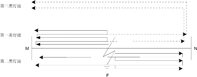
[0035] After the initial traveling wave of the current fault arrives at the measurement end, there will be a complex catadioptric process, such as figure 1 As shown, from the perspective of detection of traveling waves in the direction of initial reverse polarity, catadioptric traveling waves can be divided into the following three main types:

[0036] A type of traveling wave: a traveling wave that travels continuously between the fault point and the measurement terminal at the local end;

[0037] The second type of traveling wave: the traveling wave that continuously travels between the opposite end of the measurement end and the fault point and returns to the M end;

[0038] Three types of traveling wave: one type of traveling wave transmitted through the fault point and reflected back at the opposite end of the measurement end;

[0039] The type of busb...


PUM


Abstract

The invention discloses a method for identifying a traveling wave in an initial reversed polarity direction. The method can be used for effectively identifying the wave head of the traveling wave in the initial reversed polarity direction under various conditions and is not influenced by factors such as the fault type, modulus transmission, modulus attenuation and the like. The method comprises the following steps of: 1, starting to carry out wave recording by traveling wave distance measuring equipment; 2, detecting a fault initial traveling wave, recording time t1 that the fault initial traveling wave reaches a home terminal of a measuring terminal and extracting a traveling signal in an interval of [0.2tMF+2tNF] after the fault initial traveling wave, wherein tMF and tNF respectively represent required time that the fault traveling wave is transmitted to the home terminal of the measuring terminal from a fault point and required time that the fault traveling wave is transmitted to an opposite terminal of the measuring terminal from the fault point; 3, actually measuring the values of Delta t1 and Delta t2 and discriminating the property of the traveling wave in the initial reversed polarity by a criterion on the basis of a formula that Delta t1/Delta t2=f(LMF); 4, if a special point is generated, identifying the special point by a criterion on the basis of function features between the Delta t1 and a fault distance; and 5, if an extreme case is generated in the step (4), combining an actual wave-recording line and zero mode component attenuation law to carry out further judgment.

Description

technical field [0001] The invention relates to a method for identifying traveling waves in an initial reverse polarity direction. Background technique [0002] Transmission line traveling wave fault location technology has been greatly developed and reached the level of commercialization, and has obtained a certain range of applications at home and abroad. Single-ended traveling wave fault location has low investment cost, does not require GPS system and double-ended communication, and is not affected by factors such as asynchronous startup of the double-ended hardware system and inconsistent time. It has a series of advantages. At the same time, due to the different management units of the plants and stations at both ends of the transmission line, it is inevitable to rely on the single-ended ranging method. For this reason, strengthening the understanding of single-ended traveling wave signals, mining the rich fault information it contains, and enhancing the extraction of...

Claims


Application Information

Patent Timeline
IPC IPC(8): G01R31/08
Inventor 张峰梁军
Owner SHANDONG UNIV
Why Eureka
Try Eureka