Wavelength multiplexer/demultiplexer and method of manufacturing the same

A demultiplexer and multiplexer technology, applied in the direction of instruments, optical waveguide light guides, optics, etc., can solve the problems of increased cost and complex equipment

Inactive Publication Date: 2012-01-11
FURUKAWA ELECTRIC CO LTD
View PDF7 Cites 20 Cited by
  • Summary
  • Abstract
  • Description
  • Claims
  • Application Information

AI Technical Summary

Problems solved by technology

However, these methods pose a problem of cost increase due to an increase in the number of components or steps
In addition, the above-mentioned protective film, grooves for suppressing outflow, etc. need to be provided in a chip including MZI-AWG, thereby making the device more complicated

Method used


Image

  • Wavelength multiplexer/demultiplexer and method of manufacturing the same
  • Wavelength multiplexer/demultiplexer and method of manufacturing the same
  • Wavelength multiplexer/demultiplexer and method of manufacturing the same

Examples


no. 1 example

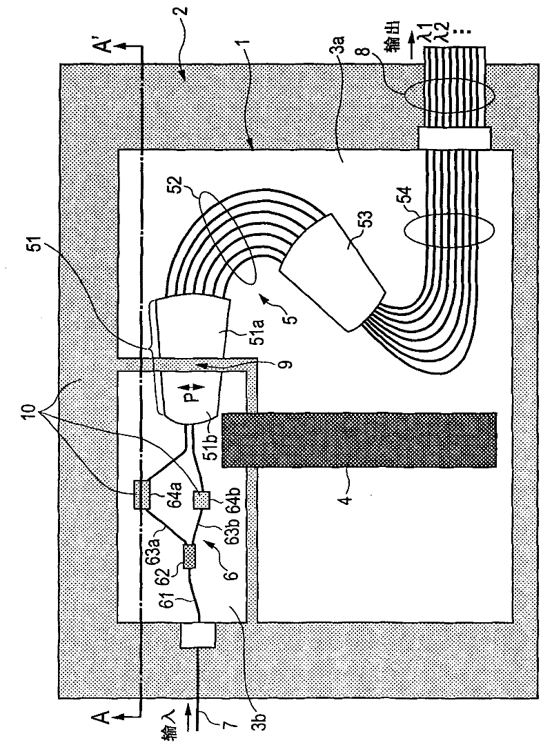
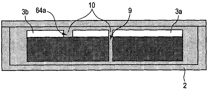
[0023] figure 1 is a top view of the wavelength multiplexer / demultiplexer according to the first embodiment, figure 2 is when along figure 1 The cross-sectional view when looking at the line A-A'.

[0024] exist figure 1 In the housing 2, a wavelength multiplexer / demultiplexer 1 (hereinafter, may be simply referred to as "chip") is provided. The wavelength multiplexer / demultiplexer 1 comprises: a first substrate part 3 a and a second substrate part 3 b, wherein the first substrate part 3 a and the second substrate part 3 b are connected to each other via a compensating member 4 . The first substrate portion 3a and the second substrate portion 3b may be formed separately, or may be separated from a single substrate to be formed.

[0025] Arrayed waveguide gratings (AWG) are formed on the first substrate portion 3a and the second substrate portion 3b. The AWG 5 includes: a slab waveguide 51 , an array waveguide 52 of a plurality of different waveguides each having a differ...

no. 2 example

[0059] In the prior art, solid resin materials have been proposed as temperature compensation materials for athermalization of MZIs, and materials in the form of oil or gel are used as refractive index matching materials between separated slab waveguides. As a compensation used in the wavelength multiplexer / demultiplexer including MZI and AWG (also referred to as "MZI-AWG") according to the first embodiment as a temperature compensation material and also as a refractive index matching material As a material, a material in liquid or gel form or a material in resin form having fluidity and plasticity will be used so as not to prevent a change in relative position between dicing chips corresponding to a change in temperature.

[0060] On the other hand, in order to obtain flat transmission band characteristics in the desired wavelength band region in the MZI-AWG, the transmission wavelength characteristics of the MZI portion and the transmission wavelength characteristics of the A...


PUM


Abstract

The invention provides a wavelength multiplexer / demultiplexer and a method of manufacturing the same. The present invention provides a wavelength multiplexer / demultiplexer comprising a Mach-Zehnder interferometer and an arrayed waveguide diffraction grating, the wavelength multiplexer / demultiplexer having a simple configuration and being capable of reducing the degradation in the temperature compensation characteristics of a temperature compensation material provided in the Mach-Zehnder interferometer or the peeling-off of the temperature compensation material, and a method of manufacturing the same. A wavelength multiplexer / demultiplexer comprises an AWG including two separated slab waveguides and an MZI including two arm waveguides. A temperature compensation groove is formed in the two arm waveguides, wherein in a space between the temperature compensation groove, and two separated slab waveguides, a compensation material, the refractive index matching that of the AWG or Mach-Zehnder interferometer, the compensation material having a temperature dependence coefficient with a sign different from that of the temperature dependence coefficient of the waveguide core and having plasticity or fluidity, is filled.

Description

technical field [0001] The present invention relates to a wavelength multiplexer / demultiplexer and a manufacturing method thereof, and more particularly to a wavelength multiplexer / demultiplexer realizing athermalization and a manufacturing method thereof. Background technique [0002] As a method for suppressing the temperature dependence of the transmission wavelength of an arrayed waveguide grating (AWG) and realizing athermalization, two methods have been mainly proposed and put into practical use. [0003] The first method for achieving athermalization is a method in which grooves intersecting the optical path are provided in an arrayed waveguide of AWG or a slab waveguide, and in which there will be a negative temperature dependence of the refractive index and a temperature of The absolute value of the dependence is several tens of times the temperature dependence coefficient of the refractive index of the material (generally silica-based glass) that makes up the waveg...

Claims


Application Information

Patent Timeline
Patent Type & Authority Applications(China)
IPC IPC(8): G02B6/12G02B6/13
CPCG02B6/1203
Inventor 川岛洋志奈良一孝长谷川淳一
Owner FURUKAWA ELECTRIC CO LTD
Why Eureka
Try Eureka