Stacked secondary battery and method of manufacturing the same

A secondary battery, laminated technology, applied in secondary battery manufacturing, secondary battery, electrode manufacturing, etc., can solve problems such as difficult and reliable stamping, and achieve the effects of reduced shedding, high adhesion strength, and excellent charge and discharge characteristics

Inactive Publication Date: 2010-02-03
NEC ENERGY DEVICES LTD
View PDF0 Cites 22 Cited by
  • Summary
  • Abstract
  • Description
  • Claims
  • Application Information

AI Technical Summary

Problems solved by technology

[0007] In addition, the punching method can cut off a predetermined electrode in a short time, but there is also a problem that, for the coated part of the active material, due to the thickness difference between the coated part and the uncoated part, Due to the resulting step difference, it is difficult to reliably stamp with a single stamping action using a die, and after stamping, the operator needs to perform final processing by hand

Method used


Image

  • Stacked secondary battery and method of manufacturing the same
  • Stacked secondary battery and method of manufacturing the same
  • Stacked secondary battery and method of manufacturing the same

Examples


Embodiment 1

[0049] Prepare 63 parts by mass of lithium manganese composite oxide with a number average particle diameter of 15 μm, 4.2 parts by mass of acetylene black with a number average particle diameter of 7 μm, 2.8 parts by mass of polyvinylidene fluoride, and 30 parts by mass of N-methyl-2-pyrrolidone Partially constituted slurry.

[0050] Make the uncoated length of 20 mm over the entire width of the aluminum foil with a thickness of 20 μm and a width of 150 mm for the current collector, apply intermittently with a coating length of 130 mm, dry and press to form a positive electrode with a thickness of 180 μm active material layer.

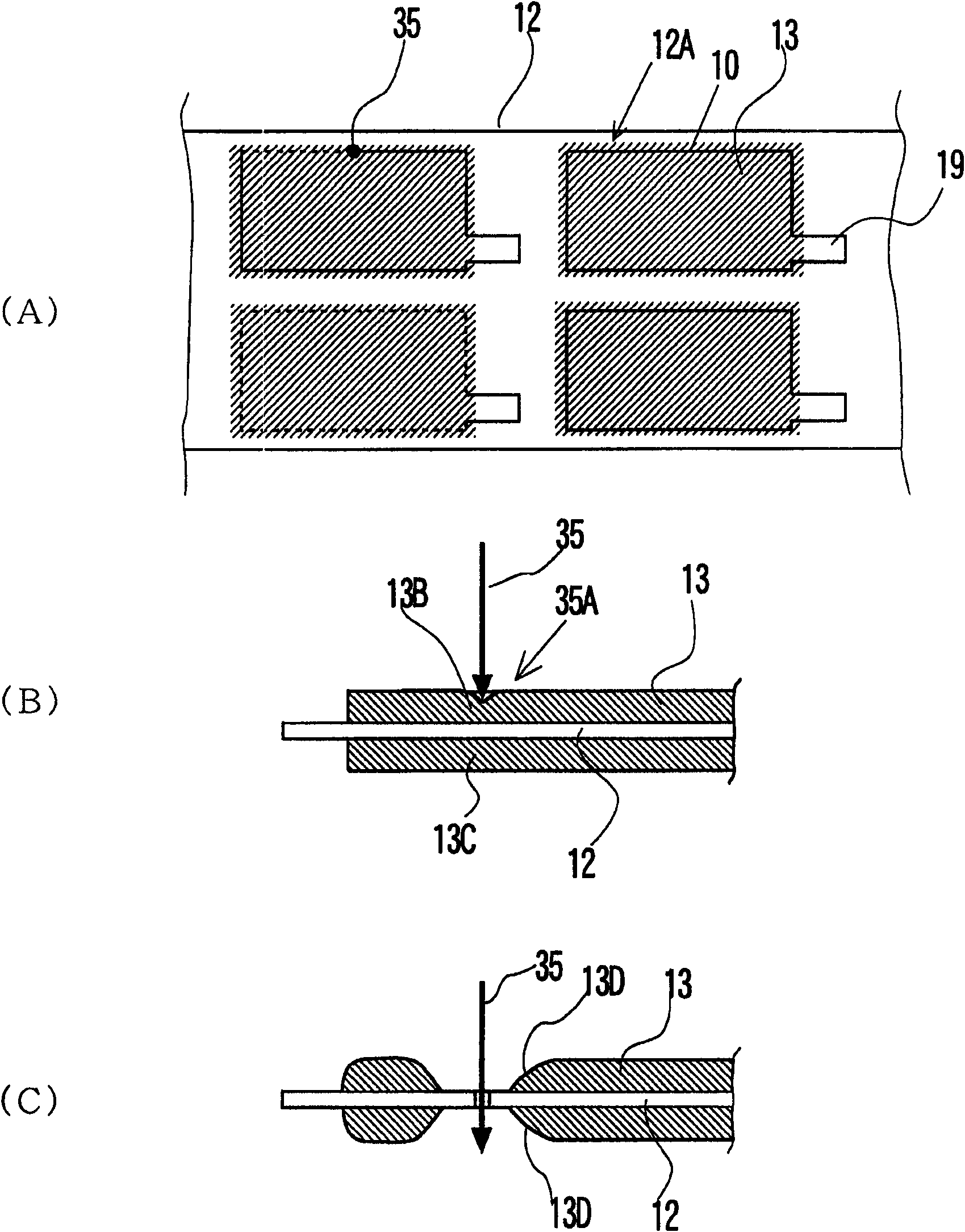
[0051] Electrode lead-out terminals were formed on the uncoated part with a width of 13 mm and a length of 17 mm, and were irradiated under the irradiation conditions of a spot diameter of 12 μm, a laser output of 20 W, and a laser repetition frequency of 20 kHz to 100 kHz using a YAG laser with a laser wavelength of 1060 nm. In addition, cutting was...

Embodiment 2

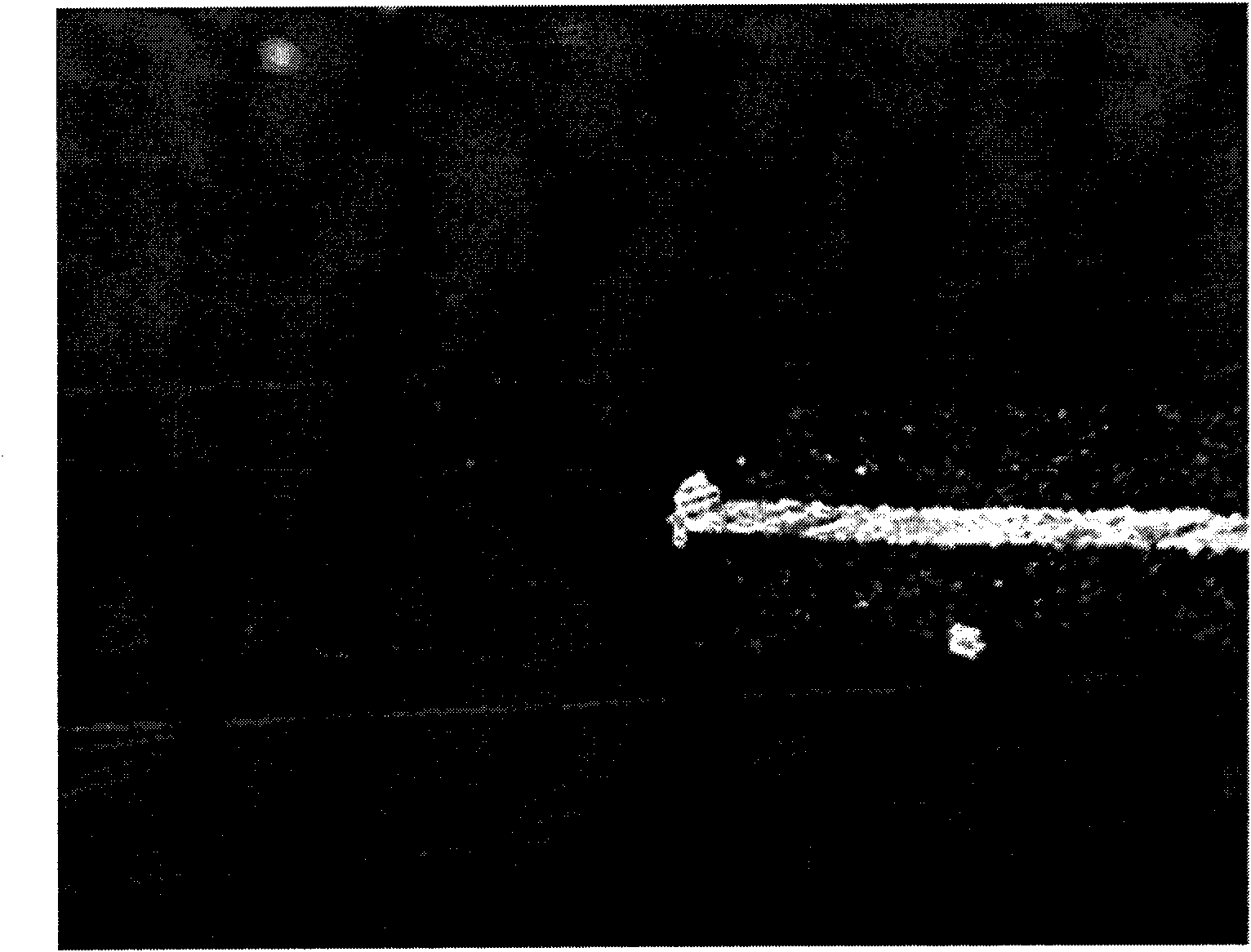
[0054] Except that the relative moving speed of the laser beam and the positive electrode active material layer is 40 mm / sec, the same section of the positive electrode obtained by cutting in the same manner as in Example 1 was photographed, and the Figure 4 The result is shown.

Embodiment 3

[0060] Preparation is composed of 49 parts by mass of graphite with a number average particle diameter of 10 μm, 0.5 parts by mass of acetylene black with a number average particle diameter of 7 μm, 3.5 parts by mass of polyvinylidene fluoride, and 47 parts by mass of N-methyl-2-pyrrolidone slurry.

[0061] Make the uncoated length of 20 mm over the entire width of the copper foil with a thickness of 10 μm and a width of 150 mm for the current collector, apply intermittently with a coating length of 130 mm, dry and press to form a 112 μm thick copper foil. Negative electrode active material layer.

[0062] In the uncoated part, an electrode lead-out terminal is formed with a width of 13mm and a length of 15mm. Using a YAG laser with a laser wavelength of 1060nm, the spot diameter is 12μm, the laser output is 20W, and the relative movement speed of the laser and the negative electrode active material layer is 20mm. Cutting was performed by irradiating laser twice at a rate of ...


PUM


Abstract

A stacked secondary battery is formed by laying plate-shaped positive electrodes and plate-shaped negative electrodes one on the other by way of separators, wherein a collector is disposed at the front end of the end facet of each of the positive electrodes or the negative electrodes as viewed in a direction orthogonal relative to the stacking direction and has an active substance layer formed onthe collector by applying slurry of particles of an active substance with a gap separating it from the front end or the electrode active substance layer is made to show a thickness varying from the front end toward the inside.

Description

technical field [0001] The present invention relates to a laminated battery in which a battery element in which flat positive electrodes and negative electrodes are laminated with a separator interposed therebetween is sealed. Background technique [0002] Lithium-ion batteries with large charge-discharge capacity and the like are widely used in portable battery-using devices such as mobile phones. In addition, in applications such as electric vehicles, electric bicycles, electric tools, and power storage, secondary batteries with large charge-discharge capacity and excellent efficiency are also required. [0003] Among these high-power batteries, a laminate type battery is used in which flat positive electrodes and negative electrodes are stacked with separators interposed therebetween. In a lithium ion battery, as a positive electrode, a positive electrode in which an aluminum foil serving as a current collector is coated with lithium transition metal composite oxide part...

Claims


Application Information

Patent Timeline
Patent Type & Authority Applications(China)
IPC IPC(8): H01M10/00H01M10/36H01M10/40H01M4/64H01M4/02H01M10/04H01M10/38H01M4/04H01M4/13H01M4/139H01M4/70
CPCY02E60/122H01M10/0525Y02T10/7011H01M10/0413H01M4/139Y02E60/10Y10T29/4911Y02P70/50H01M10/0585H01M2220/10H01M2220/20Y02T10/70
Inventor 猪濑耐大道寺孝夫
Owner NEC ENERGY DEVICES LTD
Why Eureka
Try Eureka