
Method and system for tuning a gas turbine and gas turbine including such a system

A technology of gas turbines and turbines, which is applied in the direction of turbine/propulsion fuel delivery system, fuel control of turbine/propulsion device, charging system, etc., to achieve the effects of improving acceleration time, reducing the risk of stalling, and reducing the stall margin

Active Publication Date: 2012-01-11
SN DETUDE & DE CONSTR DE MOTEURS DAVIATION S N E C M A
View PDF3 Cites 13 Cited by
  • Summary
  • Abstract
  • Description
  • Claims
  • Application Information

AI Technical Summary

Problems solved by technology

Today, in some circumstances and especially during continuous speed changes, there may be significant discrepancies between the estimated thermodynamic state of the turbojet engine and its true state, which makes it necessary to compare the calculated gate Add extra margin to the limit value or dimensioning of the compressor

Method used


Image

  • Method and system for tuning a gas turbine and gas turbine including such a system
  • Method and system for tuning a gas turbine and gas turbine including such a system
  • Method and system for tuning a gas turbine and gas turbine including such a system

Examples


Embodiment Construction

[0037] The following description is made within the scope of the aircraft turbojet engine described in the present patent application. However, the invention may also be applied to other types of aviation gas turbines, such as helicopter turbines, or to industrial turbines.

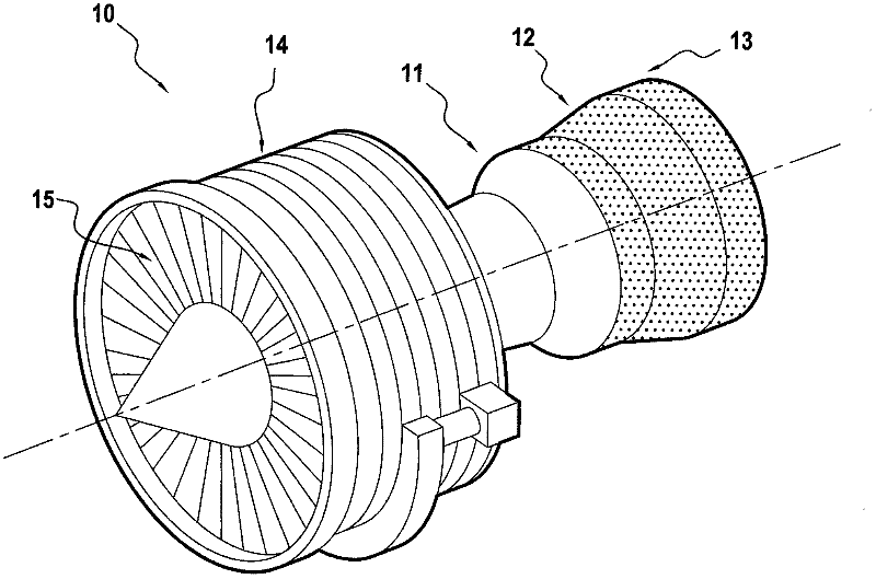
[0038] figure 1 A twin-shaft turbojet engine 10 for an aircraft is shown diagrammatically, comprising a combustion chamber 11 equipped with injectors, combustion gases in the combustion chamber 11 driving a high-pressure turbine 12 and a low-pressure turbine 13 . The high-pressure turbine 12 is connected by a high-pressure shaft to a high-pressure compressor 14 supplying compressed air to the combustion chamber 11 , while the low-pressure turbine 13 is connected by a low-pressure shaft to a fan 15 located at the inlet of the turbojet.

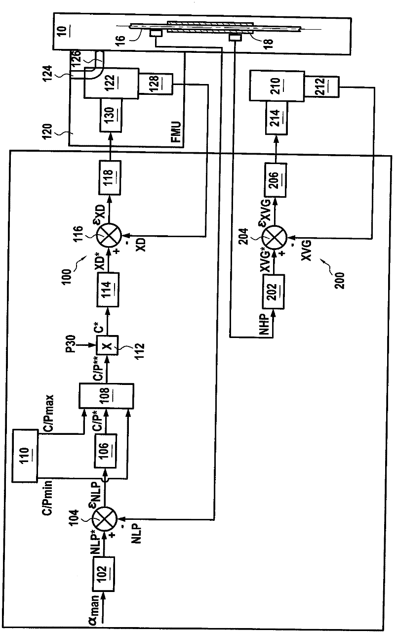
[0039] An embodiment of the control system according to the prior art is figure 2 shown.

[0040] Said control system comprises a main control loop 100 for forcing the...


PUM


Abstract

The invention relates to a system and to a method for tuning a gas turbine having a compressor system (10) with at least one portion (210) having a variable shape, a combustion chamber and a turbine assembly, wherein said method includes: setting a flow setpoint (C*) for the fuel to be fed into the combustion chamber on the basis of a target mode of the gas turbine, calculating threshold values (C / Pmin', C / Pmax') for maintaining the fuel flow setpoint value within a given range, the threshold values depending on a thermodynamic state of the gas turbine, and controlling the position of the variably-shaped portion by controlling an actuator on the basis of the deviation between position information (XGV) representative of the instantaneous position and setpoint position information (XGV*), the threshold values being adjusted automatically by a real-time calculation on the basis of the instantaneous position information of the variably-shaped portion or the deviation (epsilon XGV) between the detected position information and the setpoint position information.

Description

Background technique [0001] The present invention relates to the control of gas turbines, in particular, but not exclusively, gas turbines for aeroengines, especially turbojet engines. [0002] In turbojet engines, several control loops are provided, more particularly: [0003] - The main control loop for forcing the speed of the turbojet to be synchronized to a speed set point dependent on the desired thrust by acting on the flow rate of the fuel delivered to the combustion chamber of the gas turbine . [0004] -Local control loop for forced synchronization of the position of the variable geometry section. [0005] In a turbojet engine with multiple spools, such as a low pressure (LP) spool (compressor and turbine) and a high pressure (HP) spool, the magnitude servoed by the main control loop may be the connection between the low pressure turbine and the low pressure compressor The speed of the axis of rotation of the NLP. Other quantities may be used, notably the engine ...

Claims


Application Information

Patent Timeline
IPC IPC(8): F02C9/52F02C9/54
CPCY02T50/671F02C9/52F05D2270/101F02C9/54Y02T50/60
Inventor 克里斯蒂安·鄂卢梭
Owner SN DETUDE & DE CONSTR DE MOTEURS DAVIATION S N E C M A
Learn More