Multi-blade fan

A blower and multi-blade technology, applied in mechanical equipment, engine manufacturing, machine/engine, etc., can solve problems such as waste

Active Publication Date: 2012-01-11
MITSUBISHI ELECTRIC CORP
View PDF7 Cites 9 Cited by
  • Summary
  • Abstract
  • Description
  • Claims
  • Application Information

AI Technical Summary

Problems solved by technology

In this way, in the configuration of changing the shape of the blades of the impeller, an effect is obtained on the target airflow, but waste is generated on other airflows, so there is a problem that a sufficient effect cannot always be obtained.

Method used


Image

  • Multi-blade fan
  • Multi-blade fan
  • Multi-blade fan

Examples


Embodiment Construction

[0028] Hereinafter, the present invention will be described in detail with reference to the drawings. In addition, this invention is not limited to this embodiment. In addition, the constituent elements of the present embodiment include a replaceable and easily replaceable structure while maintaining the identity of the invention. In addition, a plurality of modification examples described in this embodiment can be combined arbitrarily within the range that those skilled in the art can easily imagine.

[0029] [Multi-blade blower]

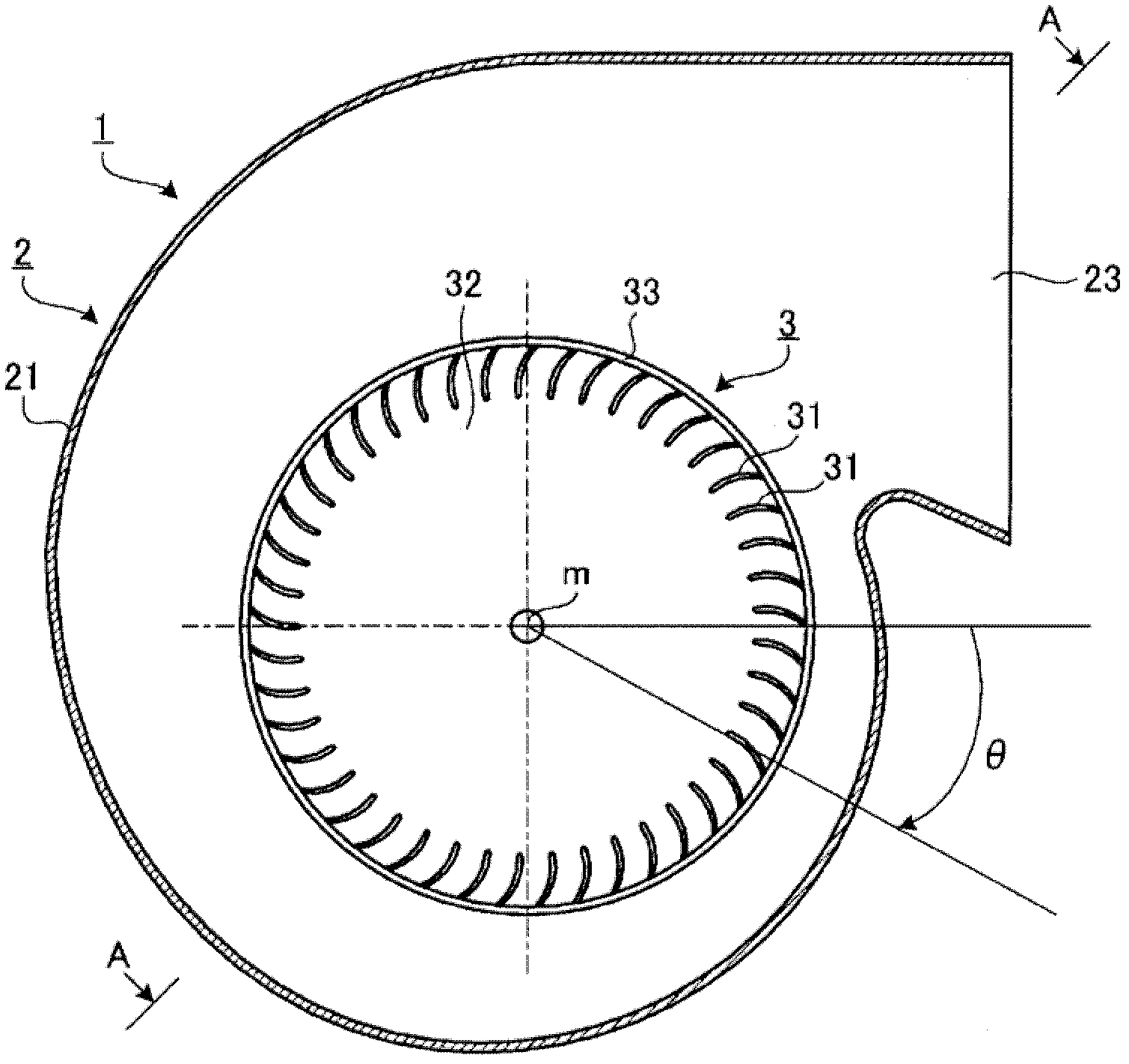
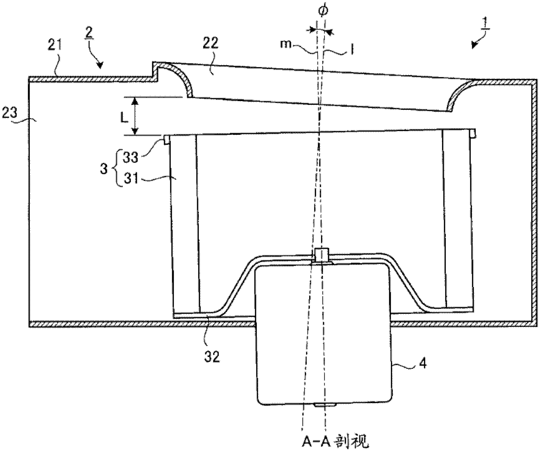
[0030] The multi-blade blower 1 is a blower having a multi-blade impeller (Sirocco fan), and is used, for example, in air conditioners, duct fans, ventilation fans, and the like. In addition, the multi-blade blower 1 may be a one-side suction type or a two-side suction type. In this embodiment, as an example, the multi-blade blower 1 adopting a one-side suction type will be described.

[0031] The multi-blade blower 1 has a housing 2, an impell...


PUM


Abstract

A multi-blade fan having improved noise performance and air delivery performance. A multi-blade fan (1) is provided with a scroll type casing (2) having a bell-mouth-shaped suction opening (22), and also with a blade wheel (3) equipped with annularly arranged blades (31) and housed in the casing (2) with the rotation axis (m) of the blade wheel directed to the suction opening (22) of the casing (2). In the multi-blade fan (1), the center axis (l) of the suction opening (22) and the rotation axis (m) of the blade wheel (3) have a positional relationship in which the axes cross each other at a tilt angle f or a positional relationship in which the axes are twisted relative to each other, and this results in a gap L between the suction opening (22) and the blade wheel (3) increasing from the rotation axis (m) of the blade wheel (3) toward the vicinity of a discharge opening (23) of the casing (2).

Description

technical field [0001] The present invention relates to a multi-blade blower, more specifically, to a multi-blade blower capable of improving noise performance or air supply performance. Background technique [0002] A general multi-blade blower includes: a scroll-type housing having a bell-mouth-shaped suction port; and an impeller accommodated in the housing. The impeller is a multi-blade impeller (Sirocco fan) in which a plurality of blades are arranged in a ring shape, and its rotating shaft faces the suction port of the casing and is accommodated in the casing. [0003] Here, in a structure in which the central axis of the suction port and the rotation shaft of the impeller are coaxial, inertial force acts on the air flowing from the suction port to the impeller. Accordingly, in the impeller, the air tends to flow deviated toward the vicinity of the main plate (plate that supports the blades). Then, the velocity distribution of the air passing between the blades (the ...

Claims


Application Information

Patent Timeline
Patent Type & Authority Applications(China)
IPC IPC(8): F04D29/44F04D29/66
CPCF04D29/162F04D29/441B60H1/00471F04D29/4213F04D29/4226F05D2250/51F04D17/08F04D29/44F04D29/66F04D29/054
Inventor 冈本一辉迫田健一菊地仁
Owner MITSUBISHI ELECTRIC CORP
Why Eureka
Try Eureka