Swing stamping mechanism

A stamping mechanism and stamping machine technology, applied in the direction of feeding device, positioning device, storage device, etc., can solve the problems of many corner waste, low production efficiency, waste of raw materials, etc., to reduce the cutting process, improve production efficiency, reduce The effect of corner scrap

Active Publication Date: 2012-01-18
靖江市易凯通风设备有限公司
View PDF4 Cites 26 Cited by
  • Summary
  • Abstract
  • Description
  • Claims
  • Application Information

AI Technical Summary

Problems solved by technology

When stamping, the stamping die stamps step by step along the extension direction of the steel strip, which not only produces more corner waste (such as Image 6 Shown is a schematic diagram o

Method used


Image

  • Swing stamping mechanism
  • Swing stamping mechanism
  • Swing stamping mechanism

Examples


Embodiment Construction

[0029] The content of the present invention will be described in detail below in conjunction with the accompanying drawings and specific embodiments:

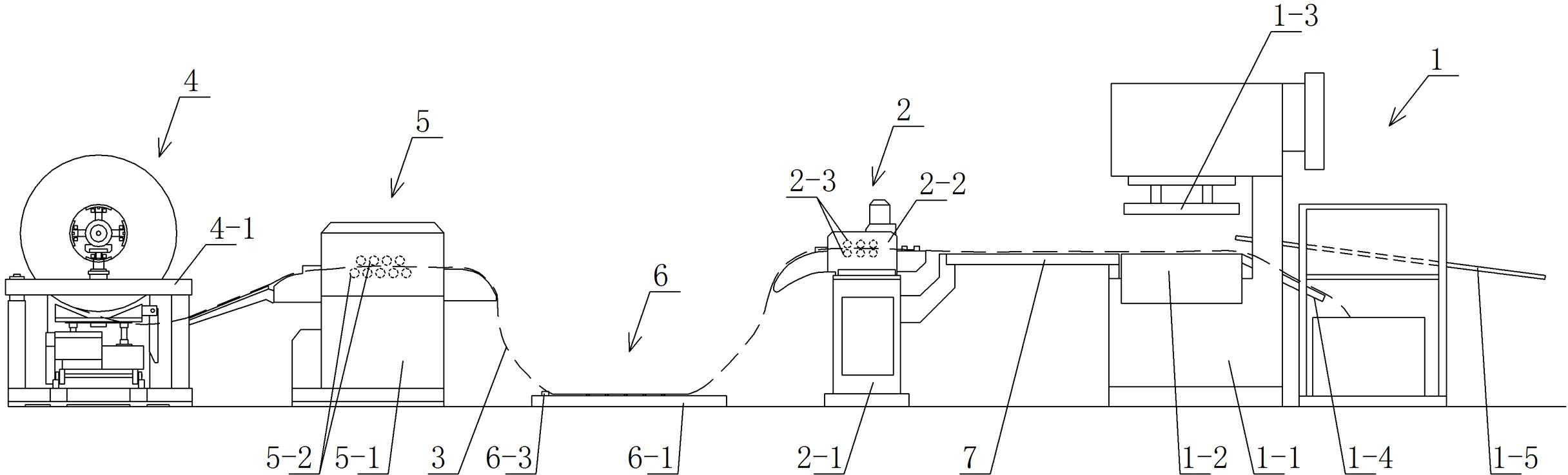
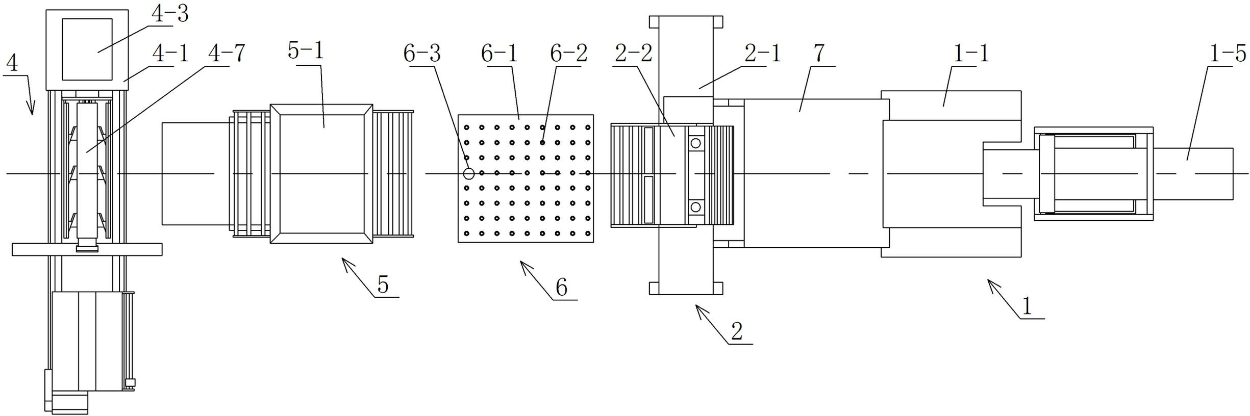
[0030] Such as Figure 1-Figure 5 Shown is a swing stamping mechanism provided by the present invention, which includes a stamping machine 1, the stamping machine includes a punch frame 1-1, a lifting stamping die installed on the punching frame 1-1, and is used to drive the lifting stamping die to carry out The lifting control device for punching work is characterized in that it also includes a numerical control device and a yaw feeder 2 arranged on the rear side of the punching machine 1. The yaw feeder 2 includes a fixed bracket 2-1, which is installed on the fixed bracket The movable frame 2-2 on the frame 2-1 and capable of translating laterally relative to the fixed bracket 2-1 along the direction perpendicular to the advancing direction of the material (such as a steel strip), is connected to the fixed bracket 2-1 and th...


PUM


Abstract

The invention relates to a swing stamping mechanism, which comprises a stamping machine, wherein the stamping machine comprises a stamping frame, a lifting stamping die arranged on the stamping frame as well as a lifting control device for driving the lifting stamping die to carry out stamping work. The swing stamping mechanism is characterized by further comprising a numerical control device and a deflection feeding machine arranged at the rear side of the stamping machine; the deflection feeding machine comprises a fixed bracket, a movable stand, a transverse translation driving device and a material forward conveying device, wherein the movable stand is arranged on the fixed bracket and can be used for transversely translating along a direction vertical to the forward direction of materials relative to the fixed bracket; the transverse translation driving device is connected between the fixed bracket and the movable stand and is used for driving the movable stand to transversely translate; the material forward conveying device is arranged on the movable stand and can be used for conveying the materials to move along the forward direction of the materials; and the numerical control device is respectively connected with the lifting control device, the transverse translation driving device and the material forward conveying device for transmitting a control command. According to the swing stamping mechanism disclosed by the invention, work procedures can be reduced, the production efficiency can be improved and the waste of raw materials can be reduced.

Description

technical field [0001] The invention relates to a swing stamping mechanism, which is applicable to products such as stamping motor stator and rotor. Background technique [0002] At present, the existing stamping mechanism for stamping motor stators or rotors must first unroll the entire steel coil into steel strips, and then cut the steel strips into slender strips before performing the stamping work. The strip-shaped steel strips are fed into the lifting stamping die to stamp the stator or rotor. When stamping, the stamping die stamps step by step along the extension direction of the steel strip, which not only produces more corner waste (such as Figure 6 Shown is a schematic diagram of the waste produced after stamping by the existing stamping mechanism), resulting in a large waste of raw materials, and many processes, time-consuming and laborious, low production efficiency and high cost. Contents of the invention [0003] In order to solve the above-mentioned proble...

Claims


Application Information

Patent Timeline
IPC IPC(8): B21D22/06B21D43/02B21D45/02B21C51/00H02K15/02
CPCY02P80/30
Inventor 刘茂见
Owner 靖江市易凯通风设备有限公司
Why Eureka
Try Eureka