
Belt material non-destructive coiling tensioner

A non-damaging and tensioning technology, applied in the direction of coiling strip, thin material handling, transportation and packaging, etc., to improve the coiling quality and solve the effect of scratches

Active Publication Date: 2013-07-17
HANGZHOU HENGLI CUTTING EQUIP
View PDF4 Cites 0 Cited by
  • Summary
  • Abstract
  • Description
  • Claims
  • Application Information

AI Technical Summary

Problems solved by technology

In this way, due to the sliding friction between the felt pad and the belt material, the surface of the belt material will inevitably be scratched

Method used


Image

  • Belt material non-destructive coiling tensioner
  • Belt material non-destructive coiling tensioner

Examples


Embodiment Construction

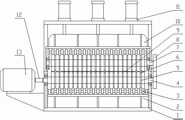
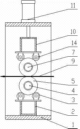
[0015] like figure 1 , figure 2 As shown, a coiling and tensioning machine without damage to the strip, the coiling and tensioning machine includes a frame 1, an upper main shaft 7, a lower main shaft 4, a plurality of inert rubber wheels 5 and a plurality of friction discs 6, and an upper main shaft 7 and the lower main shaft 4 are respectively arranged on the upper and lower sides of the frame 1 through bearings, and one end of the lower main shaft 4 is connected with a motor 13 through a coupling 12, and the motor 12 is set as an anti-torque control mode, and the output of the motor 13 is in the same direction as the rotation direction of the lower main shaft 4 In the opposite torque, the other end of the lower main shaft 4 is in transmission connection with the upper main shaft 7 through a gear 8 . The plurality of inert rubber wheels 5 are evenly distributed on the upper main shaft 7 and the lower main shaft 4, and the inert rubber wheels 5 are connected with the upper ...


PUM


Abstract

The invention relates to a belt material sub-section production line coiling tensioner, specifically to a belt material non-destructive coiling tensioner. The coiling tensioner comprises a frame, an upper main shaft, a lower main shaft, a plurality of inert rubber wheels and a plurality of frictional disks, wherein one end of the lower main shaft is connected with a motor, the motor is set in a reactive torque control mode, the motor outputs a torque reverse to a rotation direction of the lower main shaft, and the other end of the lower main shaft is in drive connection with the upper main shaft through a gear; the plurality of inert rubber wheels are uniformly distributed on the upper main shaft and the lower main shaft, the inert rubber wheels on the upper main shaft or the lower main shaft can rotate independently, the inert rubber wheels on the upper main shaft is opposite to the inert rubber wheels on the lower main shaft, and a channel for the belt material is formed between tworows of the inert rubber wheels; the frictional disks are arranged between the inert rubber wheels, the frictional disks rotate with the rotation of the upper main shaft or the lower main shaft, and end faces of the frictional disks are in frictional contact with the end faces of the inert rubber wheels; and a pressure apparatus for pressing the inert rubber wheels to compress the belt material tightly is arranged on the frame. With the tensioner, the problem of scratch is solved, and the coiling quality of the sub-section production line is improved.

Description

technical field [0001] The invention relates to a coiling and tensioning machine for a strip slitting production line. Background technique [0002] The slitting production line is to cut the wide coil into multiple narrow strips, and then use the coiler to harvest the multiple narrow strips at the same time. The coiling tensioner applies a certain tension to each narrow strip before the coiler is wound. Tension to ensure that the harvested rolls are neat, tight and not loose. [0003] The conventional coiling tensioning machine adopts the technique of placing felt pads on the upper and lower sides of the strip material, pressing the felt pads to clamp the strip material, and friction between the felt pad and the strip material to generate tension when the strip material is coiled. In this way, due to the sliding friction between the felt pad and the strip material, the surface of the strip material will inevitably be scratched. Contents of the invention [0004] In orde...

Claims


Application Information

Patent Timeline
Patent Type & Authority Patents(China)
IPC IPC(8): B65H23/26
Inventor 李建峰李民强
Owner HANGZHOU HENGLI CUTTING EQUIP
Learn More