
Rubber roller auxiliary rolling machine and auxiliary rolling device

A technology of rubber rollers and coiling aids, which is applied in the directions of coiling strips, transportation and packaging, thin material processing, etc. It can solve the problems of difficult installation and debugging, the failure of the whole equipment to work normally, and high processing precision requirements, and achieve convenience The effects of processing and manufacturing, easy maintenance, and simplified structure

Inactive Publication Date: 2014-09-17
OUDA YICHANG ELECTROMECHANICAL EQUIP
View PDF6 Cites 0 Cited by
  • Summary
  • Abstract
  • Description
  • Claims
  • Application Information

AI Technical Summary

Problems solved by technology

The processing precision is high, and the installation and debugging are difficult. Any problem in any link will cause the whole equipment to fail to work normally.

Method used


Image

  • Rubber roller auxiliary rolling machine and auxiliary rolling device
  • Rubber roller auxiliary rolling machine and auxiliary rolling device
  • Rubber roller auxiliary rolling machine and auxiliary rolling device

Examples


Embodiment 1

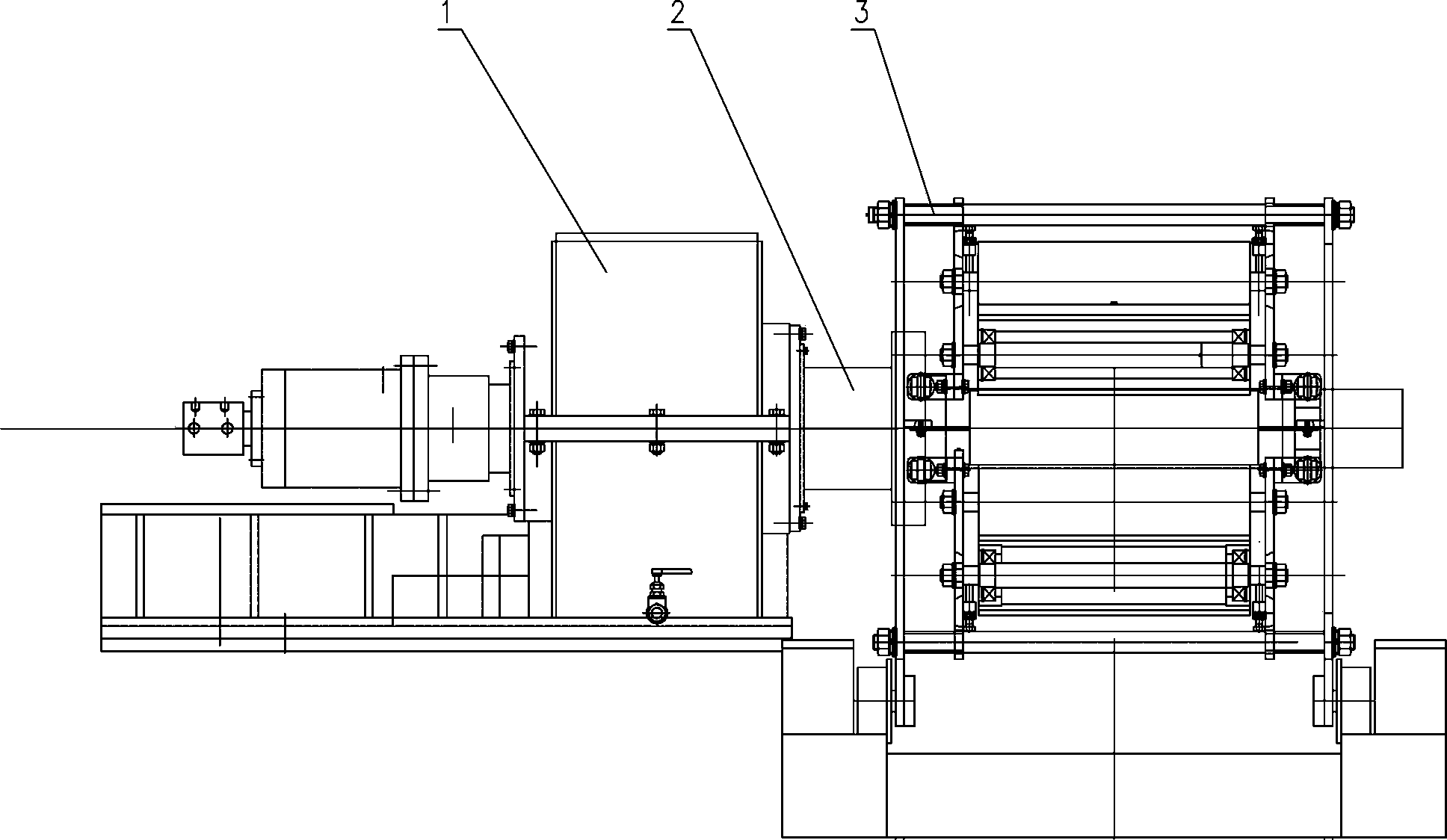
[0030] Such as figure 1 Among them, the coiler 1 is located on one side of the auxiliary coiler 3, the reel 2 is installed on the coiler 1, and the reel 2 is driven to rotate by the coiler 1. Utilize the coiler 3 to tightly hold the reel 2, so that the steel strip is tightly wound on the reel.

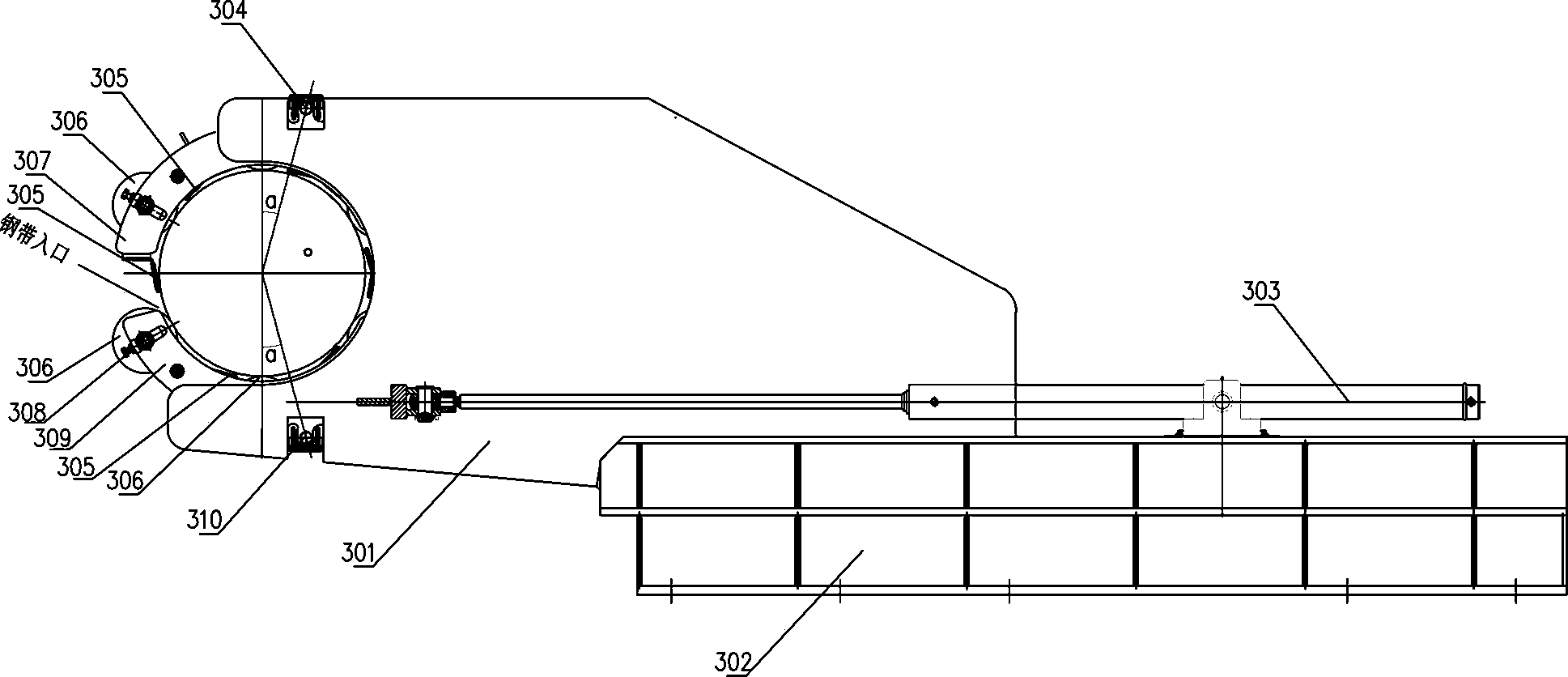
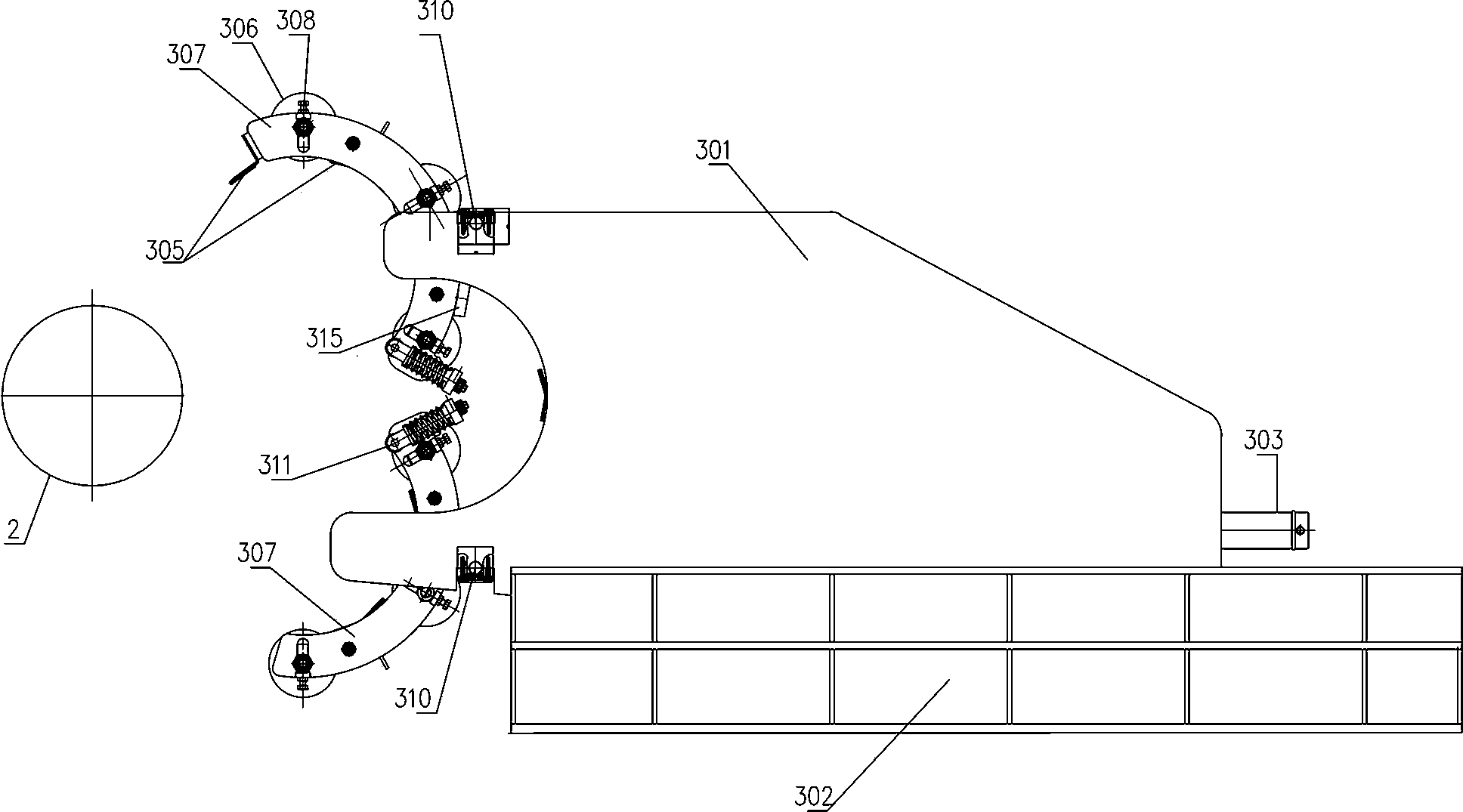
[0031] Such as figure 2 , 3 Among them, a rubber roller rolling machine includes a base 302, a host 301 is slidably installed on the base 302, a drive cylinder 303 is fixedly installed on the base 302, and the piston rod of the drive cylinder 303 is connected to the host 301; The expansion and contraction of the cylinder 303 drives the main machine 301 to reciprocate on the base 302. The driving cylinder 303 can be a hydraulic cylinder or an air cylinder, which is also the power mechanism of the present invention. Preferably, the main machine 301 slides horizontally, but for occasions with special requirements, It is also feasible for the host 301 to slide along an inclined surface...

Embodiment 2

[0042] Such as Figure 2~4 Among them, a roll-assisting device is a roll-assisting structure that can be used alone, and it includes an upper swing arm 307 and a lower swing arm 309 that are hingedly connected to the main machine 301, and an upper swing arm 307 and a lower swing arm 309 are formed between the upper swing arm 307 and the lower swing arm 309 to accommodate rolls. In the space of cylinder 2, a plurality of rubber rollers 306 protruding from the inner wall are movably installed on the upper swing arm 307 and the lower swing arm 309, and a plurality of guide plates are movably installed between the rubber rollers 306 and on the outer end of the upper swing arm 307 305; in this example, the upper swing arm 307 and the lower swing arm 309 can be driven independently by a driving device, such as a gear mechanism, an air cylinder or a hydraulic cylinder, to complete the opening and closing action.

[0043] preferred as image 3 Among them, an extension section 313 is ...


PUM


Abstract

The invention provides a rubber roller auxiliary rolling machine and an auxiliary rolling device. The rubber roller auxiliary rolling machine comprises a base, wherein a main machine is slidably arranged on the base, a driving cylinder is fixedly arranged on the base, a piston rod of the driving cylinder is connected with the main machine, an upper swing arm and a lower swing arm are hinged to the main machine, a space for containing a coiling block is formed between the upper swing arm and the lower swing arm, a plurality of rubber rollers protruding the inner wall are movably arranged on each of the upper swing arm and the lower swing arm, and a plurality of guide plates are movably arranged among the rubber rollers and the outer side end of the upper swing arm. The invention provides the rubber roller auxiliary rolling machine and the auxiliary rolling device, and the rubber rollers arranged on the upper swing arm and the lower swing arm are used for replacing belt auxiliary rolling structures in the prior art, so that the structure is simplified, processing and manufacturing are convenient, and the maintenance is also very convenient. After the structure is adopted, the wrap angle of the coiling block is also increased, and the coiling quality is improved. The guide plates are arranged, so that interference to the ends of belt materials among the rubber rollers is overcome, and the full-wrap-angle compressing of the belt materials on the coiling block is realized.

Description

technical field [0001] The invention relates to the field of coiling equipment for steel strips, in particular to a rubber roller coiling aid and a coiling aiding device. It is suitable for various production lines of steel, copper, aluminum, titanium, structural steel, alloy steel and stainless steel strip. Including: rolling line, tempering line, annealing line, galvanizing line, degreasing line, color coating line, finishing line, shearing line, etc. Background technique [0002] The coiling aid equipment in the prior art all adopts the structure of belt form, and wrapping angle is generally less than 270 °, and is provided with several oil cylinders and more complicated hinge, even has parts such as gear. The processing accuracy is high, and the installation and debugging are difficult. Any problem in any link will cause the entire equipment to fail to work normally. Contents of the invention [0003] The technical problem to be solved by the present invention is to ...

Claims


Application Information

Patent Timeline
Patent Type & Authority Applications(China)
IPC IPC(8): B65H18/06
Inventor 陈建雄姜亦红吴定川
Owner OUDA YICHANG ELECTROMECHANICAL EQUIP
Learn More