Polysilicon reducing furnace with novel nozzles

A reduction furnace and polysilicon technology, applied in silicon and other directions, can solve the problems of high production cost and high energy consumption for polysilicon reduction, and achieve the effects of improving production efficiency, rational layout and reducing heat loss.

Inactive Publication Date: 2012-01-18
CHINA ENFI ENGINEERING CORPORATION
View PDF6 Cites 2 Cited by
  • Summary
  • Abstract
  • Description
  • Claims
  • Application Information

AI Technical Summary

Problems solved by technology

Since the silicon core inside the reduction furnace needs to be maintained at 1050°C-1100°C for production, and the outside is cooled with a cooling jacket, the use of 12 pairs of rods, 18 pairs of rods and other reduction furnaces to produce polysilicon reduction consumes a lot of energy and high production costs. It does not meet the requirements of the current fierce market competition, and there is an urgent need for the emergence of a new type of reduction furnace that can save energy and reduce consumption.

Method used


Image

  • Polysilicon reducing furnace with novel nozzles
  • Polysilicon reducing furnace with novel nozzles
  • Polysilicon reducing furnace with novel nozzles

Examples


Embodiment Construction

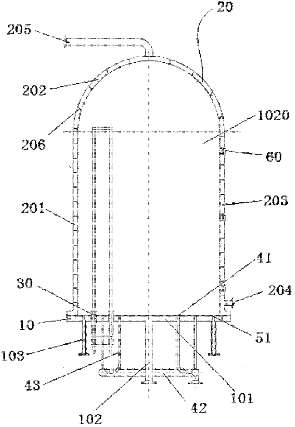
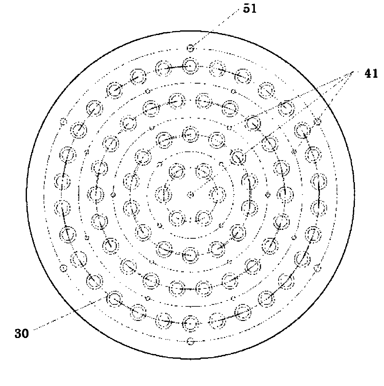
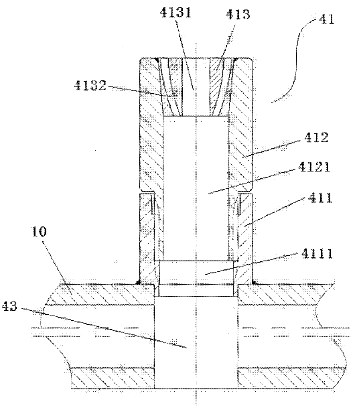
[0027] Embodiments of the present invention are described in detail below, examples of which are shown in the drawings, wherein the same or similar reference numerals designate the same or similar elements or elements having the same or similar functions throughout. The embodiments described below by referring to the figures are exemplary only for explaining the present invention and should not be construed as limiting the present invention.

[0028] In describing the present invention, it should be understood that the terms "center", "longitudinal", "transverse", "upper", "lower", "front", "rear", "left", "right", " The orientations or positional relationships indicated by "vertical", "horizontal", "top", "bottom", "inner", "outer", etc. are based on the orientation or positional relationships shown in the drawings, and are only for the convenience of describing the present invention and simplifying Describes, but does not indicate or imply that the device or element referred...


PUM


Abstract

The invention discloses a polysilicon reducing furnace which comprises a chassis, a furnace body, 36 pairs of electrodes, an air inlet system and an exhaust system, wherein the 36 pairs of electrodes are arranged on the chassis and are respectively distributed on first, second, third and fourth concentric circumferences; each nozzle comprises a base, a drainage portion and a diversion portion; a first air inlet cavity is formed on the base; the drainage portion is connected with the upper end of the base; a second air inlet cavity is formed on the drainage portion and is communicated with the first air inlet cavity; the cross section area of the second air inlet cavity is smaller than that of the first air inlet cavity; the diversion portion is connected with the upper end of the drainage portion; a central orifice is formed in the middle of the diversion portion; a plurality of lateral orifices surround the central orifice and are uniformly distributed on the diversion portion along the circumferential direction; and the central orifice and the plurality of lateral orifices are communicated with the second air inlet cavity. According to the polysilicon reducing furnace disclosed by the embodiment of the invention, the heat energy can be reasonably utilized, and the production efficiency of the reducing furnace can be simultaneously improved.

Description

technical field [0001] The invention relates to the technical field of polysilicon production, in particular to a polysilicon reduction furnace with a novel nozzle. Background technique [0002] The polysilicon reduction furnace is the core equipment for producing the final product in the production of polysilicon, and it is also the key link that determines the system capacity and energy consumption. Therefore, the design and manufacture of polysilicon reduction furnace directly affects the product quality, output and production cost. Under the influence of the global economic crisis, the price of polysilicon continued to drop, the industry profit was continuously compressed, and the market competition became increasingly fierce. Therefore, effectively reducing polysilicon energy consumption, improving product quality, and increasing production efficiency are important issues that polysilicon production enterprises need to solve at present. [0003] At present, the produc...

Claims


Application Information

Patent Timeline
Patent Type & Authority Applications(China)
IPC IPC(8): C01B33/03
Inventor 严大洲肖荣晖毋克力汤传斌汪绍芬姚心
Owner CHINA ENFI ENGINEERING CORPORATION
Why Eureka
Try Eureka