Visual testing device for liquid metal fluidity and testing method based on it

A liquid metal and testing device technology, applied in flow characteristics, measuring devices, instruments, etc., can solve the problems of low testing accuracy, invisible pouring speed and pouring temperature, etc., and achieve reliable control, visual recording, and high precision Effect

Inactive Publication Date: 2012-01-18
HARBIN UNIV OF SCI & TECH
View PDF12 Cites 21 Cited by
  • Summary
  • Abstract
  • Description
  • Claims
  • Application Information

AI Technical Summary

Benefits of technology

This patented technology uses an image capturing technique for measuring how well liquids behave when poured into containers or other objects quickly without being affected too much during their production time. It allows us to record all that happens while it's still flowable but also has fast-acting controls over its cooling period. By analyzing this data we are able to determine whether there will be any issues affecting the quality of the final product before they reach consumers through mass distribution channels like retail stores.

Problems solved by technology

This patents describes various ways to measure how well liquids behave before they cool down from their molten state. One way involves mechanically checking if these materials have enough fluidness at room temperatures without actually melting them up again after being casted onto another material called an investment layer made of ceramic fiber cloth (CFF). Another approach uses specialized equipment like vibrating tools instead of relying solely upon gravity alone. These techniques aim to provide precise data about the properties of the fluorescent powder-filled resin composition.

Method used


Image

  • Visual testing device for liquid metal fluidity and testing method based on it
  • Visual testing device for liquid metal fluidity and testing method based on it

Examples


specific Embodiment approach 1

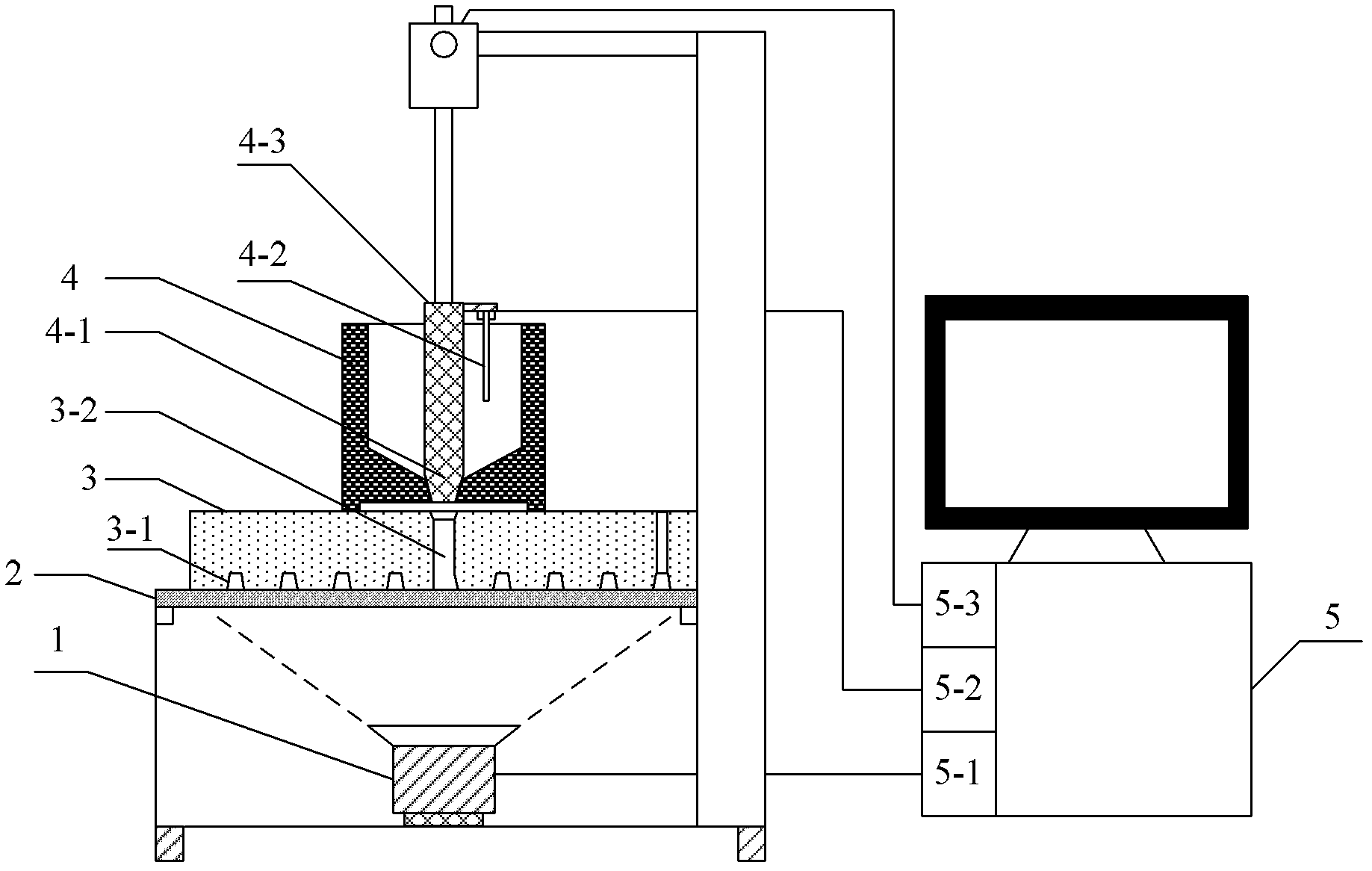
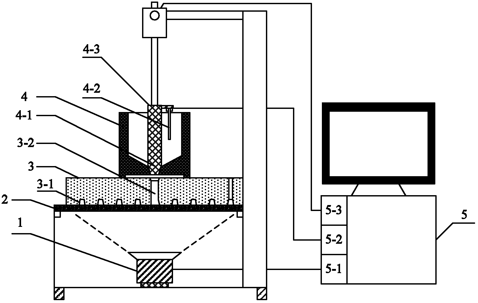
[0012] Specific implementation mode 1. Combination figure 1 Illustrate this specific embodiment, liquid metal fluidity visualization testing device, it comprises CCD camera 1, fluidity testing cavity 3-1, insulation sprue cup 4, temperature sensor 4-2 and computer 5, fluidity testing cavity 3 -1 is composed of a high temperature resistant quartz glass plate 2 and a clay sand upper box 3; the bottom surface of the clay sand upper box 3 is fixed on the high temperature resistant quartz glass plate 2; the CCD camera 1 is arranged under the high temperature resistant quartz glass plate 2, and the CCD The shooting surface of the camera 1 faces the high-temperature-resistant quartz glass plate 2, and the thermal insulation sprue cup 4 is placed above the clay sand upper box 3, and the gate at the bottom of the thermal insulation sprue cup 4 corresponds to the runner on the upper part of the clay sand upper box 3; the temperature sensor 4-2 is used for collecting the temperature of t...

specific Embodiment approach 2

[0013] Embodiment 2. The difference between this embodiment and the liquid metal fluidity visualization testing device described in Embodiment 1 is that it also includes a graphite stopper rod 4-3 and a lifting device, and the graphite stopper rod 4-3 is located at In the thermal insulation sprue cup 4, it is used to close the gate at the bottom of the thermal insulation sprue cup 4. One end of the graphite stopper rod 4-3 is connected to the lifting device, and the lifting device is used to drive the graphite stopper rod 4-3 to lift sports.

[0014] In this embodiment, a computer is used to control the lifting device to perform lifting motion.

[0015] Working principle: in the present invention, the high-temperature-resistant quartz glass plate 2 is used as the lower box, and the upper box of the fluidity sample is made of clay sand, and the upper box is combined on the lower box (high-temperature-resistant quartz glass plate), thereby forming Sample cavity for testing flui...

specific Embodiment approach 3

[0019] Embodiment 3. The difference between this embodiment and the liquid metal fluidity visualization test device described in Embodiment 1 or 2 is that the fluidity test cavity is a spiral cavity, a straight rod cavity or a serpentine cavity. One of the cavities.


PUM


Abstract

Relating to testing devices for liquid metal fluidity and testing methods based on the devices, the invention provides a visual testing device for liquid metal fluidity and a testing method based on the device. The device and method provides a solution to the problem of low testing accuracy caused by invisible pouring speed and pouring temperature in present methods. The device comprises: a CCD camera arranged below a high temperature resistant quartz glass plate, an insulating pouring cup positioned over a clay sand cope flask, with the pouring gate of at the bottom of the insulating pouringcup in correspondence with the upper part of the clay sand cope flask. The testing method consists of: pouring a liquid metal into a fluidity testing cavity, and measuring the temperature; shooting an image with the CCD camera below the high temperature resistant quartz glass, and conducting computer analysis so as to obtain a test result. The device and method provided in the invention is suitable for testing liquid metal fluidity.

Description


Claims


Application Information

Patent Timeline
Owner HARBIN UNIV OF SCI & TECH
Why Eureka
Try Eureka