
Method and device for optimizing mesh point of light guide plate

A light guide plate network point and light guide plate technology, which is applied in the direction of light guide, optics, optical components, etc., to achieve the effect of shortening the development cycle and reducing the development cost

Active Publication Date: 2012-01-18
创维集团智能科技有限公司
View PDF4 Cites 32 Cited by
  • Summary
  • Abstract
  • Description
  • Claims
  • Application Information

AI Technical Summary

Problems solved by technology

[0004] The purpose of the embodiment of the present invention is to provide a method for optimizing the dots of the light guide plate, aiming to solve the problem that the existing light guide plate supplementary point design must produce a light guide plate model to verify its optical effect

Method used


Image

  • Method and device for optimizing mesh point of light guide plate
  • Method and device for optimizing mesh point of light guide plate
  • Method and device for optimizing mesh point of light guide plate

Examples


Embodiment Construction

[0020] In order to make the object, technical solution and advantages of the present invention clearer, the present invention will be further described in detail below in conjunction with the accompanying drawings and embodiments. It should be understood that the specific embodiments described here are only used to explain the present invention, not to limit the present invention.

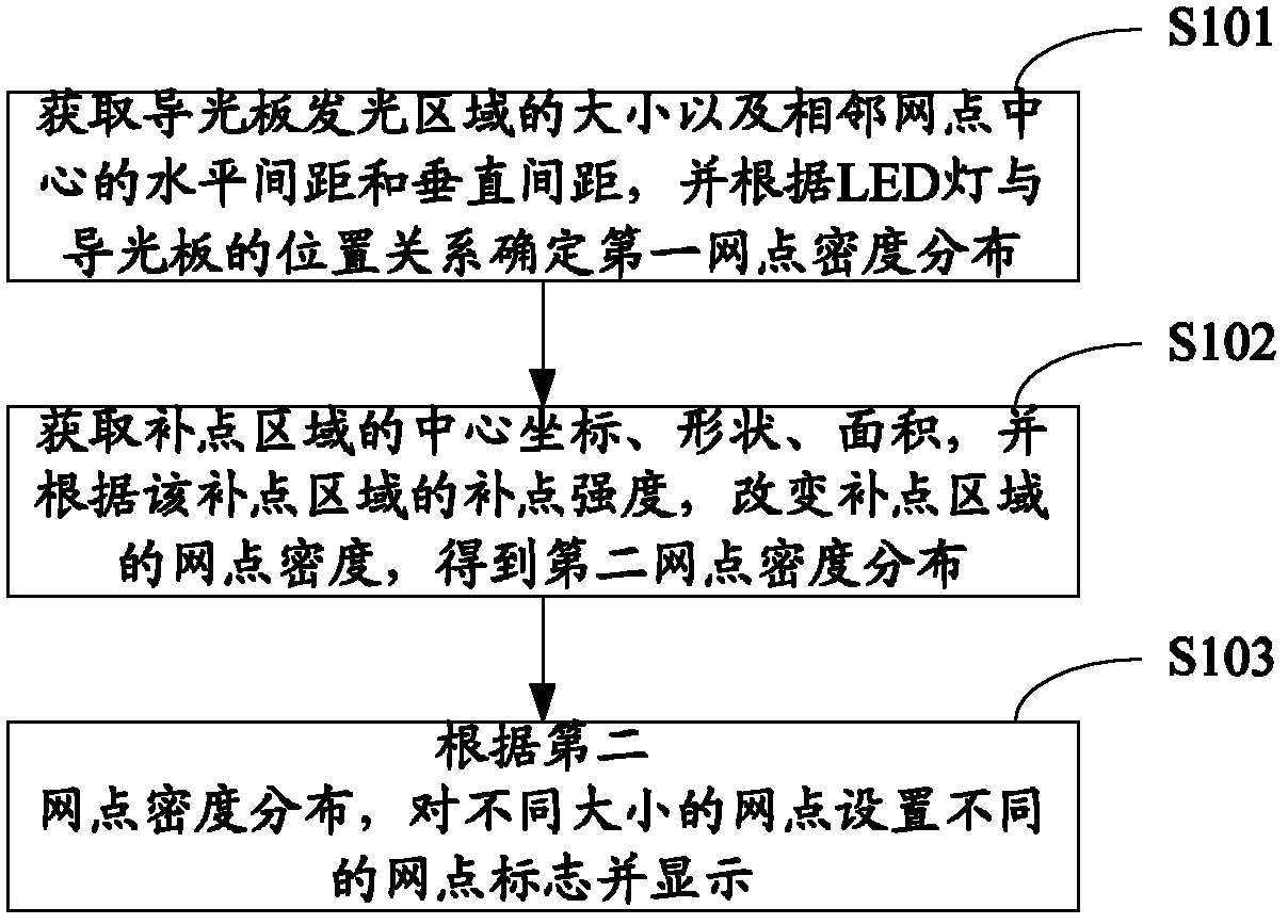
[0021] The embodiment of the present invention simulates the distribution of the dots of the light guide plate by computer, and sets different dot marks for each dot according to the simulated dot size, so that the dot size can be distinguished intuitively, so that the developer of the light guide plate can quickly according to the The simulated light guide plate is used to check the effect of supplementary points, which reduces the development cost and shortens the development cycle.

[0022] figure 1 It shows the implementation process of the method for optimizing the dots of the light guide pla...


PUM


Abstract

The invention is suitable for the field of design of mesh points of a light guide plate, and provides a method and a device for optimizing the mesh points of the light guide plate. The method comprises: determining the position of each mesh point according to the size of the light guide plate and the horizontal spacing and vertical spacing of centers of adjacent mesh points, and determining firstmesh point density distribution according to the position relationship of an LED (light-emitting diode) lamp and the light guide plate; obtaining the center coordinates, shape and area of a supplementary point area to determine the supplementary point area, changing the mesh point density of the supplementary point area according to the obtained supplementary point strength, and thus obtaining second mesh point density distribution, wherein the supplementary point strength is used for determining the ratio of changes in the sizes of mesh points in the supplementary point area; and setting different mesh point marks for the mesh points with different sizes according to the second mesh point density distribution, and displaying the mesh point marks. The distribution of the mesh points of the light guide plate can be simulated. Moreover, different mesh point marks can be set for the mesh points according to the sizes of the simulated mesh points, the sizes of the mesh points can be directly distinguished, the development cost can be reduced, and the development cycle can be shortened.

Description

technical field [0001] The invention belongs to the field of network point design of a light guide plate, and in particular relates to a method and a device for optimizing the network point of a light guide plate. Background technique [0002] The light guide plate is an important component in the light-emitting diode (Light Emitting Diode, LED) side-entry backlight module. The distribution of the dots of the light guide plate is based on the position of the LED lamp, and the distribution of the dots directly determines the optical quality of the backlight module. Performance affects the user's sensory experience. Taking a light guide plate with one side of the bottom side receiving light as an example, the dot density value on the light incident side is relatively small, and as the distance increases, the dot density gradually increases to balance the light guiding intensity of the entire light guide plate. However, it is not feasible to set the distribution of dots simply...

Claims


Application Information

Patent Timeline
Patent Type & Authority Applications(China)
IPC IPC(8): G02B27/00G02B6/00
Inventor 舒畅
Owner 创维集团智能科技有限公司
Learn More