FPGA (Field Programmable Gate Array)-based lane line detection method

A lane line detection and vanishing point technology, applied in the field of lane line detection, can solve the problems of not being able to meet such huge storage space requirements, low operating frequency and stability, increased cost and area, etc., to save storage devices and save computing time, the effect of improving reliability

Active Publication Date: 2012-01-18
NAT UNIV OF DEFENSE TECH
View PDF3 Cites 27 Cited by
  • Summary
  • Abstract
  • Description
  • Claims
  • Application Information

AI Technical Summary

Problems solved by technology

The following analysis can be done. For an image of 748×400 pixels, assuming that the unit step size of the Hough transform is 1 degree and the storage depth is 1023, the parameter space size is 180×849×1023=149M bits; if the step size is 0.5 degrees, a total of 298M bits of storage space is required, and the current FPGA-based single-chip system cannot meet such a huge storage space requirement. Therefore, literature [1] uses an external memory to store the parameters of the Hough transform
[0011] The use of external memory has the following disadvantages: first, additional cost and area need to be added; second, the system is connected to the external memory through the IO port, and the IO port is a limited resource; third, the operating frequency between the external memory and stability are much lower than on-chip internal

Method used


Image

  • FPGA (Field Programmable Gate Array)-based lane line detection method
  • FPGA (Field Programmable Gate Array)-based lane line detection method
  • FPGA (Field Programmable Gate Array)-based lane line detection method

Examples


Embodiment Construction

[0038] The present invention will be further described in detail below in conjunction with the accompanying drawings and specific embodiments.

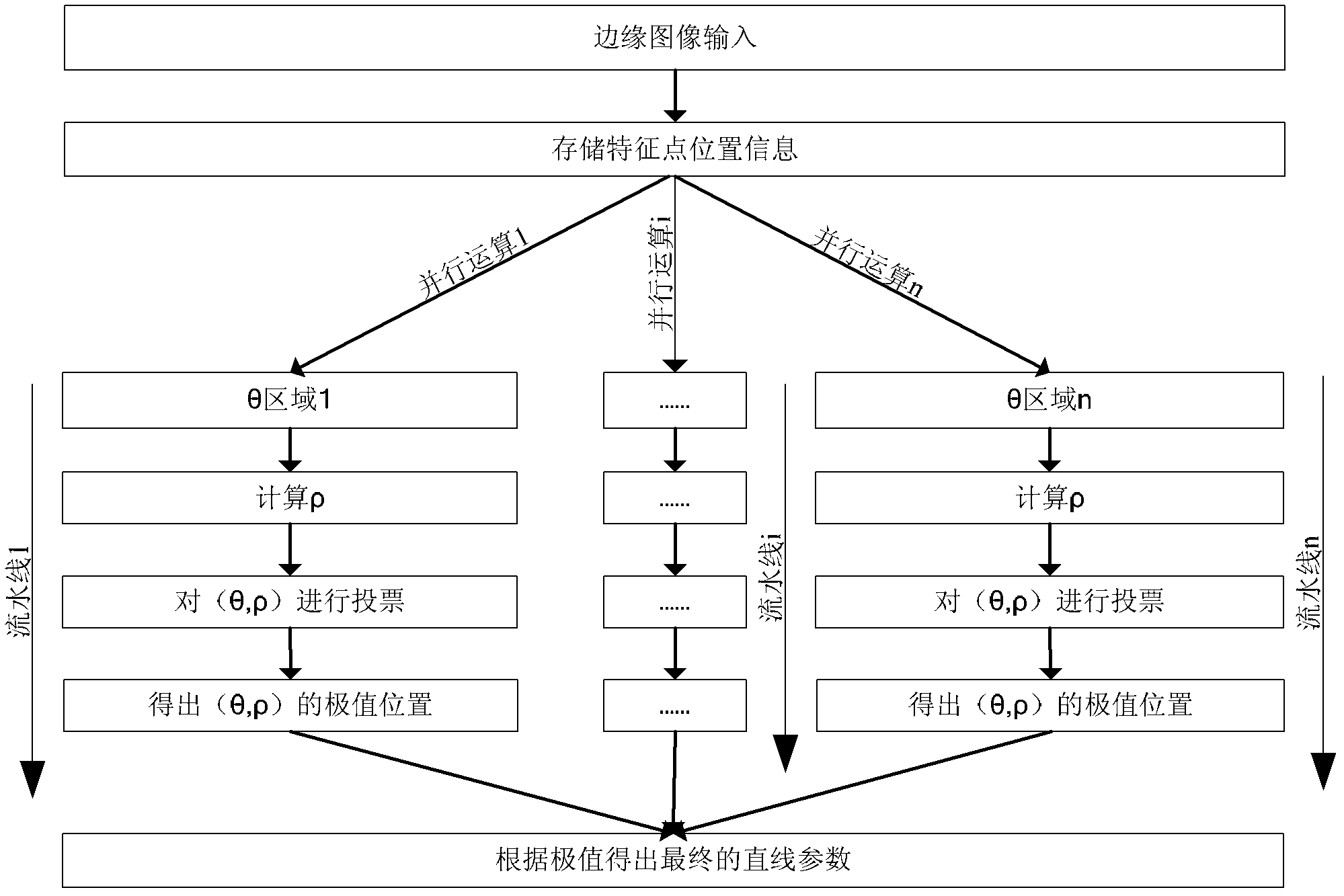
[0039] Such as Figure 7 with Figure 9 Shown, the step of the lane line detection method based on FPGA of the present invention is:

[0040] Step 1: Set the initial parameters, the initial parameters include the initial vanishing point position (x 0 ,y 0 ), parallelism n, constraint range P;

[0041] Step 2: During the driving process of the vehicle, collect the original image I of the road condition in front of the vehicle in real time i , the original image I i is the original image of frame i;

[0042] Step 3: To the original image I i Perform image preprocessing, including median filtering and edge binarization, to obtain the edge image I i edge ;

[0043] Step 4: To Edge Image I i edge Coordinate translation: the position of the vanishing point of the previous frame image is known (x i-1 ,y i-1 ), the coordinate sy...


PUM


Abstract

The invention discloses an FPGA (Field Programmable Gate Array)-based lane line detection method which comprises the steps of: 1, setting initial parameters; 2, acquiring an original image Ii of a road condition in front of a vehicle in a vehicle running process; 3, carrying out image preprocessing on the original image Ii to obtain an edge image Iiedge; 4, carrying out coodinaet translation on the edge image Iiedge, wherein a coordinate system PX2Y2 with an end point position (xi-1, yi-1) of the former frame of image as a coordinate original point is used for replacing a coordinate system PX1Y1 with a top left corner of the image as an original point so that coordinate translation is realized; 5, carrying out parallel Hough commutative operation in the PX2Y2, for the ith frame of image, obtaining rho through a formula rho=(x-xi-1)*cos(theta)+(y-yi-1)*sin(theta), when the rho meets the condition that the absolute value of rho is less than P, storing parameters (theta, rho), or otherwise, discarding; 6, finding out a position of a maximum value in a parameter space to obtain a corresponding straight line, i.e., a lane line to be detected, updating the end point (xi, yi) of the current frame; and 7, turning to the step 2. The invention has the advantages of simple principle, high efficiency, capability of reducing the demands on the storage space, reduction of hardware cost, andthe like.

Description

technical field [0001] The invention mainly relates to the field of vehicle active safety systems, in particular to a lane line detection method implemented on a programmable logic gate array (FPGA). Background technique [0002] With the development of the automobile industry, automobiles have increasingly become an important part of social production and daily life; at the same time, automobile safety issues have gradually become the focus of attention. According to statistics, about 75% of road traffic accidents are caused by human errors, and among these human-induced accidents, 19% are caused by unconscious lane deviation, and 26% are caused by forward rear-end collisions. , the occurrence of these two types of accidents is directly related to the driver's mental state, and the final performance is the driver's inaccurate estimation of the vehicle operating environment and the driver's reaction lag. The purpose of the lane departure reminder system is to remind the dri...

Claims


Application Information

Patent Timeline
Patent Type & Authority Applications(China)
IPC IPC(8): G06K9/00
Inventor 商尔科安向京李健潘升东聂一鸣刘肖琳
Owner NAT UNIV OF DEFENSE TECH
Why Eureka
Try Eureka