
Power communication distribution device

A technology of distributing devices and connecting devices, which is applied in the direction of coupling devices, components of connecting devices, circuits, etc., can solve problems such as poor contact, unstable power supply, inconvenient use, etc., to improve the stability of electrical conduction and improve contact tightness, and the effect of improving convenience

Inactive Publication Date: 2012-01-18
JIANGSU NEWHOPE RENEWABLE ENERGY S & T
View PDF16 Cites 5 Cited by
  • Summary
  • Abstract
  • Description
  • Claims
  • Application Information

AI Technical Summary

Problems solved by technology

[0003] In order to overcome the inconvenient use of the existing flexible power receiving device, which may easily lead to poor contact and unstable power supply, the present invention provides a power communication distribution device

Method used


Image

  • Power communication distribution device
  • Power communication distribution device
  • Power communication distribution device

Examples


Embodiment Construction

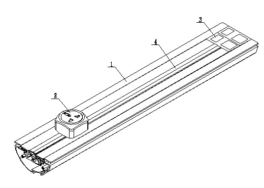
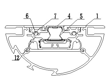
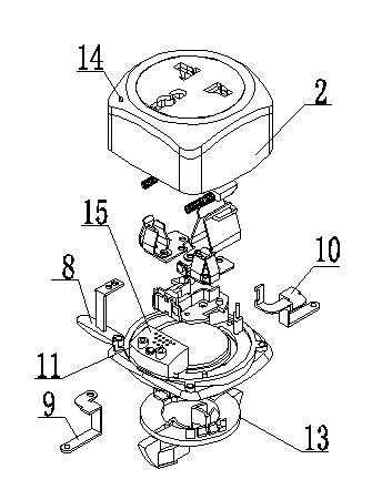
[0017] Such as figure 1 It is a structural schematic diagram of the present invention, figure 2 is a sectional view of the present invention, image 3 It is an exploded view of the plug of the present invention, Figure 4 It is a schematic diagram of the bottom of the plug of the present invention, a power communication distribution device, including a socket 1, a plug 2 and a communication interface 3, the plug 2 is inserted on the socket 1, the communication interface 3 is located at the end of the socket 1, and the upper part of the socket 1 is covered with a sealing strip 4. There are elastic positioning pieces 5, copper wires 6 and insulating Bakelite 7 inside. The plug 2 is equipped with a ground wire connector 8, a live wire connector 9 and a neutral wire connector 10. The cross section of the socket 1 is semicircular, and the plug 2 is located in the socket. One side of the horizontal plane of 1 is slidably connected with the socket 1, and a conductive indicator 11 ...


PUM


Abstract

The invention relates to the technical field of power communication equipment and particularly relates to a power communication distribution device. The power communication distribution device comprises a socket, a plug and a communication interface, wherein the section of the socket is semi-circular, the plug is positioned on one side of the horizontal plane of the socket and in sliding connection with the socket, and a conductive indicator is arranged on the plug. A semi-circular sliding body is arranged at the bottom of the plug, the existing plug-in type contact is changed to the sliding contact, and the convenience in use is greatly improved; the up-down contact way is adopted, thereby improving the contact tightness and the stability in electric conduction; and a user can know the conduction situation of a circuit in a directviewing and clear manner by virtue of the conductive indicator.

Description

technical field [0001] The invention relates to the technical field of power communication equipment, in particular to a power communication distribution device. Background technique [0002] In the home and commercial environment, the traditional electric power distribution system is provided by the receiving point, which is installed in the cavity of the wall or on the surface of the predetermined position. The location and number of such receiving points need to be selected in advance. Once selected It is difficult to change, but in actual use, often due to changes in the environment or structural adjustments, it is difficult to meet the actual needs of the power receiving points arranged in advance, and re-arranging consumes a lot of energy and manpower. cause great inconvenience. Therefore, a flexible power receiving device has appeared on the market, but this flexible power receiving device is a plug-in type, which is not only inconvenient to use, troublesome to adjus...

Claims


Application Information

Patent Timeline
IPC IPC(8): H01R25/14H01R13/46H01R13/717
Inventor 张大鹏
Owner JIANGSU NEWHOPE RENEWABLE ENERGY S & T
Learn More