Power supply real-time communication method

A real-time communication and communication technology, applied in the direction of data switching current source, data exchange details, etc., can solve the problems of difficult to be widely used, complex application technology, difficult and reliable application, etc., to achieve no need for bus conflict detection, efficient transmission speed, transmission fast effect

Active Publication Date: 2012-01-18
BEIJING GUOREN ZHENGFANG TECH
View PDF5 Cites 4 Cited by
  • Summary
  • Abstract
  • Description
  • Claims
  • Application Information

AI Technical Summary

Problems solved by technology

In China, the most widely used centralized meter reading communication method is still dominated by the 485 bus, which makes the less nodes (generally no more than 100 points) and short distance (generally hundreds of meters) originally designed for industrial automation data collection , The 485 bus communication that can standardize the wiring is difficult to apply reliably in the communication of multi-node (thousands, tens of thousands), long-distance (thousands of meters), and arbitrary distribution wiring methods
In the field of industrial automation applications, the cost of PRFBUS, CAN, HART, FF and other communication methods used in multi-node and long-distance data communication is relatively high.
In Europe, the communication method of household instruments is mainly M-BUS (Meter Bus), which can solve multi-node and long-distance communication problems, but due to its high cost and complicated application technology, it is still difficult to obtain widely used

Method used


Image

  • Power supply real-time communication method
  • Power supply real-time communication method
  • Power supply real-time communication method

Examples


Embodiment Construction

[0019] The technical problem to be solved by the present invention is to provide a transmission solution for remote IO information, especially but not limited to two-wire communication. Refer to the following figure 1 ~ Fig. 7 illustrates the two-wire system real-time communication method of the present invention.

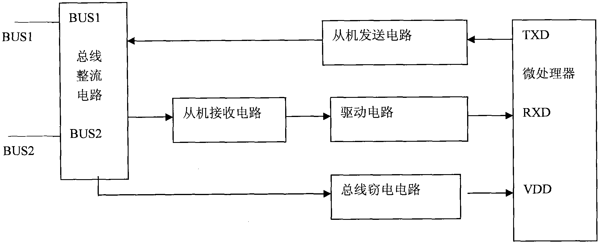
[0020] figure 1 , figure 2 Respectively show the circuit block diagrams of the preferred two-wire master and slave circuits used in the present invention;

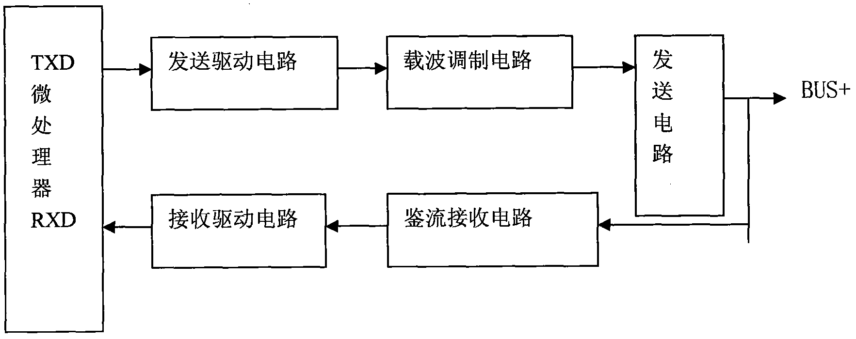
[0021] Such as figure 1 The shown two-wire host circuit (patent application number: 201020629870.2) includes:

[0022] A microprocessor, its communication sending end and communication receiving end are respectively connected to the input of the sending drive circuit and the output of the receiving drive circuit;

[0023] Sending drive circuit, the output of which is connected to the carrier modulation circuit;

[0024] A carrier modulation circuit, the output of which is connected to the sending circuit...


PUM


Abstract

The invention provides a power supply real-time communication method, which is used for mutual communication among a plurality of nodes. In the method a node is addressed by a time division multiplexing mode, and each time slot of a synchronizing pulse corresponds with a node address, wherein each time slot is divided into four time intervals by five moments from t1 to t5. After the system is initiated, the method comprises the following steps: 1, a synchronous power supply signal supplies power to all N nodes in synchronized power supply time intervals, and is delayed to the t1 moment of the first node; 2, the synchronous power supply signal is changed from high level to first low level at the t1 moment of the time slot of the corresponding node, and is delayed to t2 moment for input operation of the node until t3 moment; 3, the output state of the node is detected at t3 moment for output operation of the node until t4 moment; 4, high level of the synchronous power supply signal is maintained to charge the node in the time interval of between t4 and t5; and 5, the nodes are counted to determined whether a communication cycle is completed or not. The system circulates the operation in the performed way.

Description

technical field [0001] The invention relates to a method for real-time communication with power supply, especially a method for real-time communication with two-wire power supply, which is used for real-time digital node control communication in the fields of industrial control systems, fire protection systems, building automation, and vehicle detection technology. . Background technique [0002] At present, in the fields of industrial control, fire protection system, building automation, and vehicle detection technology, remote communication technology has not been well resolved as one of the difficult problems. In China, the most widely used centralized meter reading communication method is still dominated by the 485 bus, which makes the few nodes (generally no more than 100 points) and short distance (generally hundreds of meters) originally designed for industrial automation data collection , The 485 bus communication that can standardize the wiring is difficult to reli...

Claims


Application Information

Patent Timeline
Patent Type & Authority Applications(China)
IPC IPC(8): H04L12/10
Inventor 焦安海
Owner BEIJING GUOREN ZHENGFANG TECH
Why Eureka
Try Eureka