Network bandwidth-adaptive video stream transmission control method

An adaptive network, streaming control technology, applied in image communication, selective content distribution, electrical components, etc., can solve the same video bit rate, delay and other problems

Active Publication Date: 2012-01-18
ZHEJIANG WANLI UNIV
View PDF6 Cites 42 Cited by
  • Summary
  • Abstract
  • Description
  • Claims
  • Application Information

AI Technical Summary

Problems solved by technology

However, in reality, due to random changes in network bandwidth and video scenes, the video bit rate cannot be exactly t

Method used


Image

  • Network bandwidth-adaptive video stream transmission control method
  • Network bandwidth-adaptive video stream transmission control method
  • Network bandwidth-adaptive video stream transmission control method

Examples


Embodiment 1

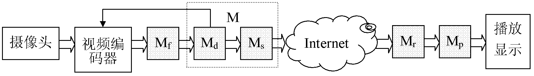
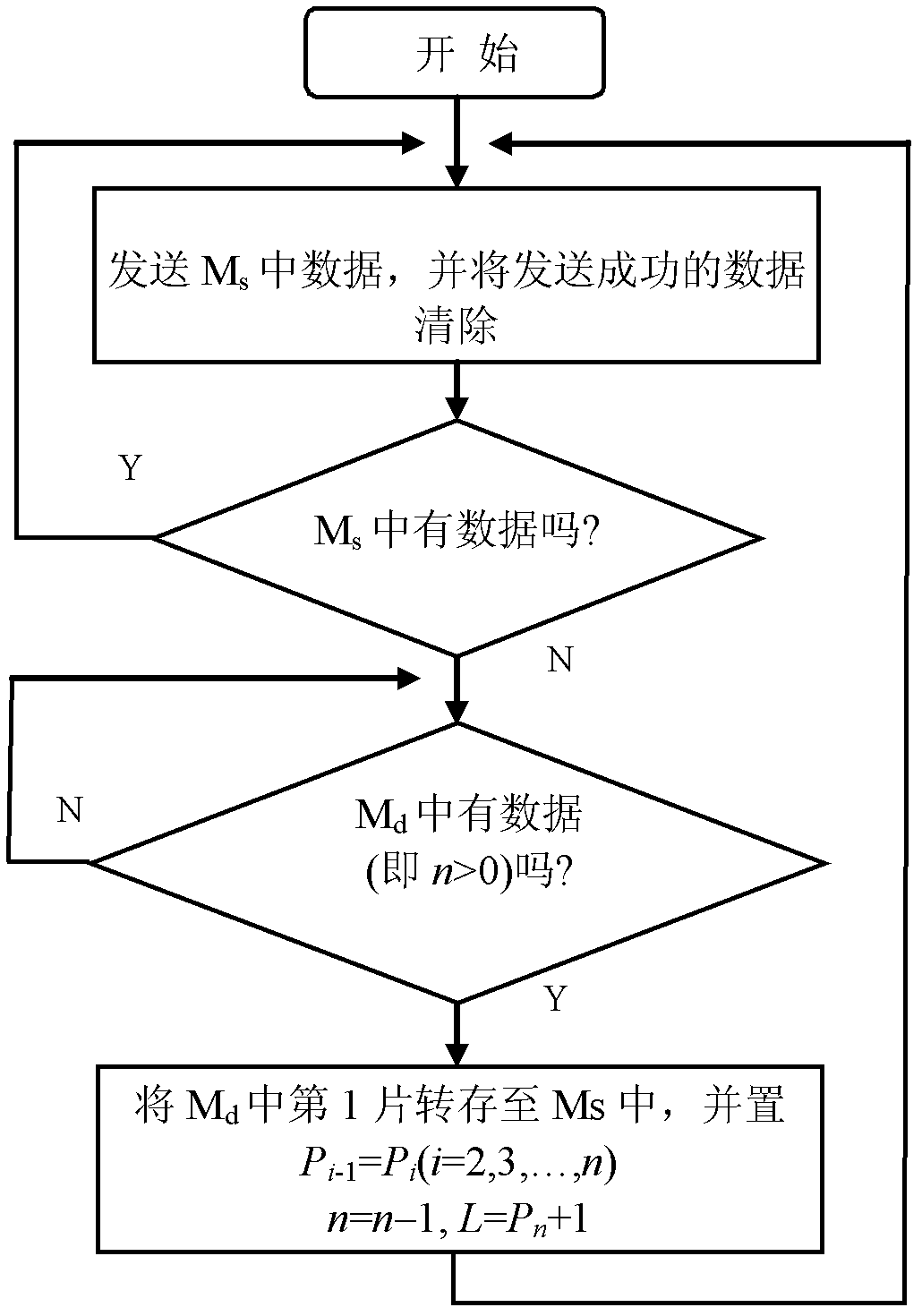
[0051] The present invention provides an adaptive network bandwidth video stream transmission control method, which divides the cache M of the sender into two: one is the video data cache, denoted as M d , used to store the video frame data from the video encoder, and the other is the video sending buffer, denoted as M s , used to temporarily store a frame of video data from the video data cache, waiting for the transmission link to send; if M d , M s The total byte length is denoted as L d , L s , then the length of the buffer M of the sender is L d +L s . figure 1 is a schematic diagram of the data transfer relationship between caches during video transmission, where M d For first-in-first-out stream buffering, M f A frame of video data buffer output by the video encoder, M r Buffer for data reception, M p Cache for video playback, the double-line arrow in the figure indicates the direction of data flow transmission, and the single-line arrow indicates the direction...

Embodiment 2

[0064] The difference from Example 1 is:

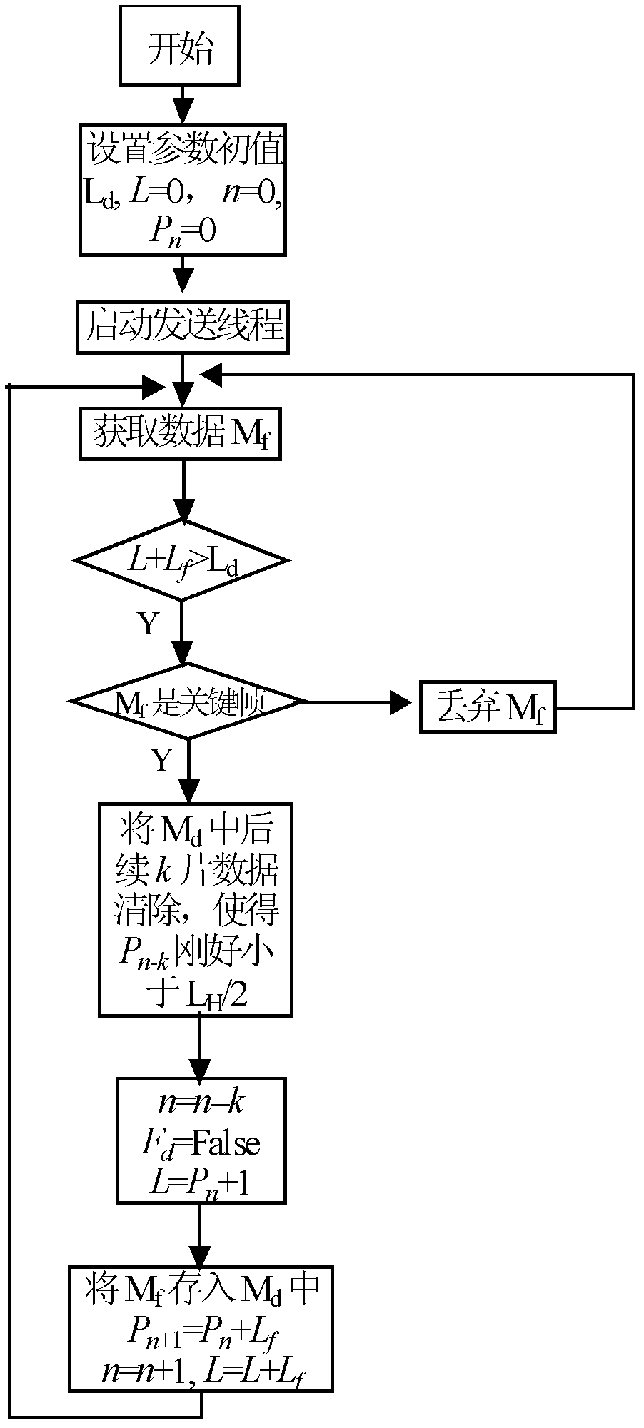
[0065] Set the video code rate output by the video encoder to multiple levels, when the video encoder has video data M f Input to video data buffer M d , detect the video data cache M d The length L of the existing data in, if when L+L f > L H , immediately notify the encoder to lower the video bit rate by one level; but within a period of time after that, when the video data cache receives the video data M f , L+L will still be detected f > L H , which may be caused by the following two reasons: ① Due to the delay in the video code rate reduction, it will take a while for L+L f will not exceed L H ;②The network bandwidth is too small, and the video bit rate must be lowered by 2 levels or above. If it is only the first case, there is no need to lower the bit rate of the video encoding, but for the second case, the video encoder must be notified to continue lowering the video bit rate.

[0066] After notifying the video encode...

Embodiment 3

[0077] Different from Example 2,

[0078] When the network bandwidth becomes larger or the video scene changes tend to be stable in the variable bit rate mode, the video bit rate will become smaller than the network bandwidth, M f Dump data to M d Send out immediately after, M d There is no accumulation of video data. Since the higher the video bit rate, the better the overall picture quality of the video stream, therefore, the control method will increase the video bit rate within the range allowed by the network bandwidth.

[0079] In Example 2, once L+L appears f > L H , the video bit rate will be lowered immediately, and if M d If there is no data in (i.e. L=0), the video code rate will be increased immediately, which may make M d The amount of accumulated data has increased dramatically. Because before M d The lack of data in the middle may be caused by the short-term bandwidth of the unstable network or the short-term stability of the video scene. When the bandwi...


PUM


Abstract

The invention relates to a network bandwidth-adaptive video stream transmission control method. In the method, a transmitter is provided with a video data buffer and a data transmission buffer, a video data input thread and a video data transmission thread which are concurrently run are set at the same time, and three main control methods for video frame loss, video code rate up-regulation and video code rate down-regulation in a video transmission process are established according to variations of a network bandwidth; a frame address array is set in the control method to realize the by-the-frame transmission and discarding of video data to avoid the occurrence of 'broken video frames' in the transmission process; and a weight accumulation method in which time is taken as a parameter is adopted by the control method to judge the variation trend of video data accumulation to ensure the regulation accuracy of a video code rate. By the method, the video code rate can be ensured to be adaptively regulated along the fluctuations of the network bandwidth or along variations of video scenes under a variable code rate; and the method can be effectively applied to real-time video monitoring in dynamic bandwidth network environments.

Description

technical field [0001] The invention relates to a video stream transmission control method for adaptive network bandwidth. Background technique [0002] At present, RTP is a commonly used protocol for streaming media transmission. However, since RTP is based on the UDP protocol without any congestion control, it needs to add a congestion control method on the application layer, so it cannot be directly applied to real-time network environments with narrow and variable bandwidth. video surveillance. In order to overcome the above problems, many literatures propose different methods. In the existing transmission control methods, there are mainly two solutions: video stream bit rate control and network transmission control. The former adjusts the encoding parameters according to the conditions of the network transmission channel to generate a video stream suitable for the current network transmission, so that the bandwidth required for video transmission is as small as possib...

Claims


Application Information

Patent Timeline
IPC IPC(8): H04N21/647
Inventor 刘高平
Owner ZHEJIANG WANLI UNIV
Why Eureka
Try Eureka