Method and apparatus for separating component of gaseous component

A component, gaseous technology, applied in separation methods, dispersed particle separation, chemical instruments and methods, etc., can solve the problems of high noise load, high space location requirements, high investment cost and energy cost, etc., and achieve operation and investment costs. low effect

Inactive Publication Date: 2014-12-17
PRIMETALS TECH AUSTRIA GMBH
View PDF5 Cites 0 Cited by
  • Summary
  • Abstract
  • Description
  • Claims
  • Application Information

AI Technical Summary

Problems solved by technology

[0005] The use of compressors for generating the lowest possible desorption pressures is not advantageous because they are not maintenance-free, cause high investment and energy costs, have a high space requirement and also cause high noise load

Method used


Image

  • Method and apparatus for separating component of gaseous component
  • Method and apparatus for separating component of gaseous component
  • Method and apparatus for separating component of gaseous component

Examples


Embodiment Construction

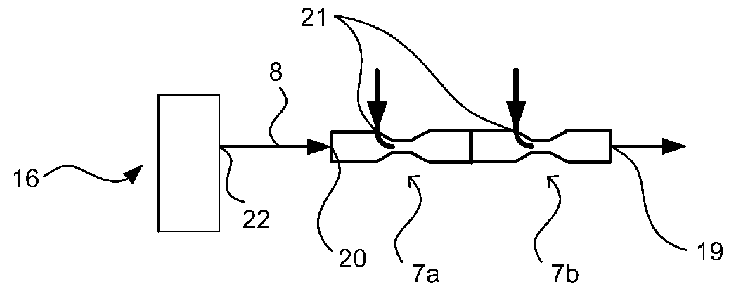
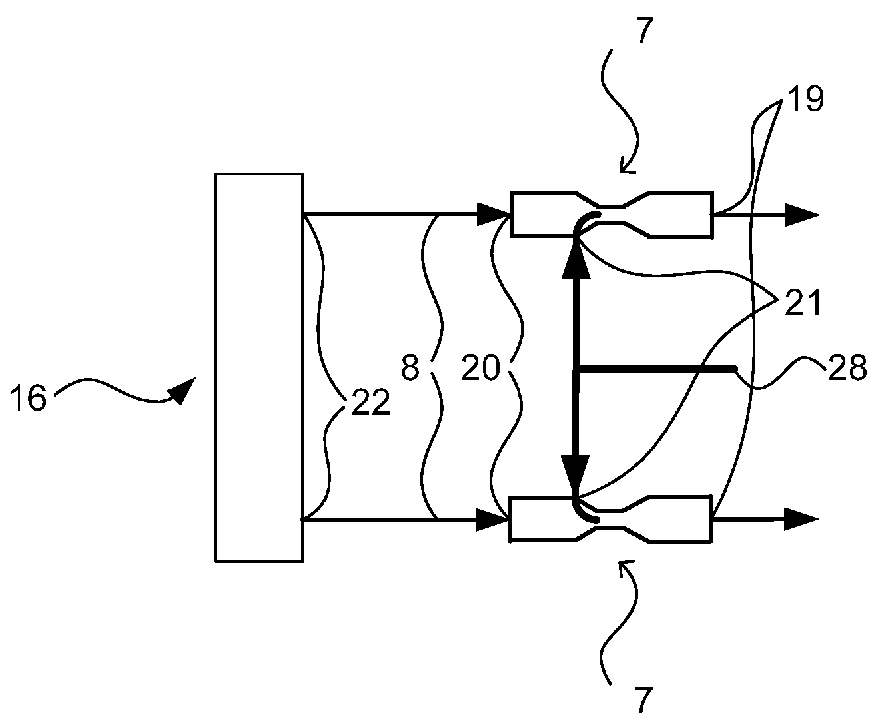
[0031] The direction of flow is indicated below by arrows.

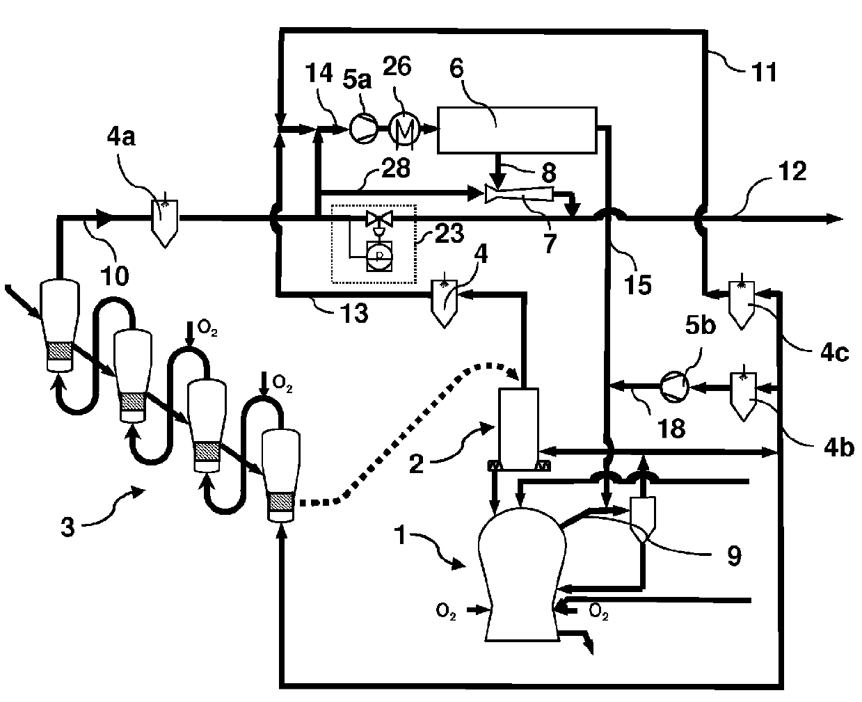
[0032] exist figure 1 A smelting reduction plant for producing liquid pig iron on the basis of fine ore is shown in . In this case, the fine ore is optionally subjected to the addition of additives in a cascade of several prereduction reactors 3 (four turbulent bed reactors are shown, optionally 2 or 3 turbulent bed reactors can also be used) pre-reduced and then loaded into the reduction reactor 2 . The loaded material is further reduced and preheated in the reduction reactor 2 . However, further reduction in the reduction reactor 2 can also be dispensed with, whereby the gas scrubber 4 and the line for the top gas 13 are omitted. The prereduction in the prereduction reactor 3 or the reduction in the reduction reactor 2 is carried out by means of the reduction gas 9 produced in the melter gasifier 1, which is introduced into the reduction reaction after dedusting in vessel 2 and successively passed through a sin...


PUM


Abstract

In a method and an apparatus for separating at least one gaseous component from a waste gas of an installation for producing liquid pig iron, liquid primary steel products or sponge iron, in a first step, a stream of the waste gas passes through at least one adsorption separator at a first pressure, whereby the gaseous component is largely separated from the waste gas and, in a second step, the gaseous component is largely removed from the adsorption separator at a second pressure, which is lower than the first pressure. The method and apparatus are maintenance-free, cause low investment and energy costs and has a lower space requirement by a method in which the second pressure or the desorption pressure is generated by at least one jet pump, which is fed a stream of a propellant gas at a third pressure, which is higher than the second pressure.

Description

technical field [0001] The invention relates to a method and a device for separating at least one gaseous constituent from the exhaust gas of a plant for producing liquid pig iron, liquid steel pre-products or sponge iron. [0002] In particular, the invention relates to a method for separating at least one gaseous constituent from the exhaust gas of a plant for producing liquid pig iron, liquid steel pre-products or sponge iron, wherein in a first step The gas stream of the exhaust gas flows through at least one adsorption separator at a first pressure, whereby the gaseous constituents are largely separated from the exhaust gas, and in a second step the gaseous constituents are separated in a ratio. Most of the second pressure at which the first pressure is lower is removed from the adsorption separator. [0003] The device for carrying out this method has at least one adsorption separator and at least one device for generating a desorption pressure. Background technique ...

Claims


Application Information

Patent Timeline
Patent Type & Authority Patents(China)
IPC IPC(8): B01D53/047
CPCB01D2259/402B01D2253/102C21B2100/06B01D2259/40056C21B5/06C21B13/0073B01D53/047B01D2257/80B01D2253/106B01D53/0446C21B2100/04B01D2256/22B01D2253/108C21B2100/02C21B2100/28C21B2100/282C21B2100/64Y02P10/122Y02P10/134Y02P10/25C21B2100/20
Inventor R.米尔纳N.赖因G.罗森福尔纳
Owner PRIMETALS TECH AUSTRIA GMBH
Why Eureka
Try Eureka