Apparatus and method for manufacturing a ball joint

A technology for ball joints and manufacturing devices, which is applied in the direction of pivot connections, household components, household appliances, etc., can solve problems such as difficult torque reduction, difficult grease filling, and narrow space, so as to improve durability and reliability, reduce The effect of torque

Active Publication Date: 2012-01-18
CENTRAL
View PDF4 Cites 5 Cited by
  • Summary
  • Abstract
  • Description
  • Claims
  • Application Information

AI Technical Summary

Problems solved by technology

For this, as figure 2 As shown, after cooling, grease is applied to the upper end of the ball head 11, and then the ball stud 10 is rotated and swung to fill the space between the outer peripheral surface of the ball head 11 and the inner peripheral surface 20a of the ball seat 20 with grease. As mentioned above, due to the contraction of the ball seat 20 during cooling, the space between the outer peripheral surface of the ball head 11 and the inner peripheral surface 20a of the ball seat 20 becomes narrow, making it difficult to fill the grease.
Thus, there arises a problem that it is difficult to reduce the torque generated between the ball stud 10 and the ball seat 20

Method used


Image

  • Apparatus and method for manufacturing a ball joint
  • Apparatus and method for manufacturing a ball joint
  • Apparatus and method for manufacturing a ball joint

Examples


Embodiment Construction

[0030] Referring to the accompanying drawings, the structure and function of the preferred embodiment of the present invention will be described in detail as follows.

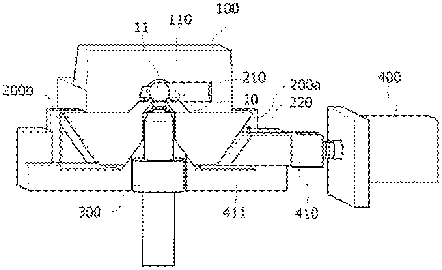
[0031] image 3 It is a partially cutaway perspective view showing a ball joint manufacturing apparatus according to an embodiment of the present invention.

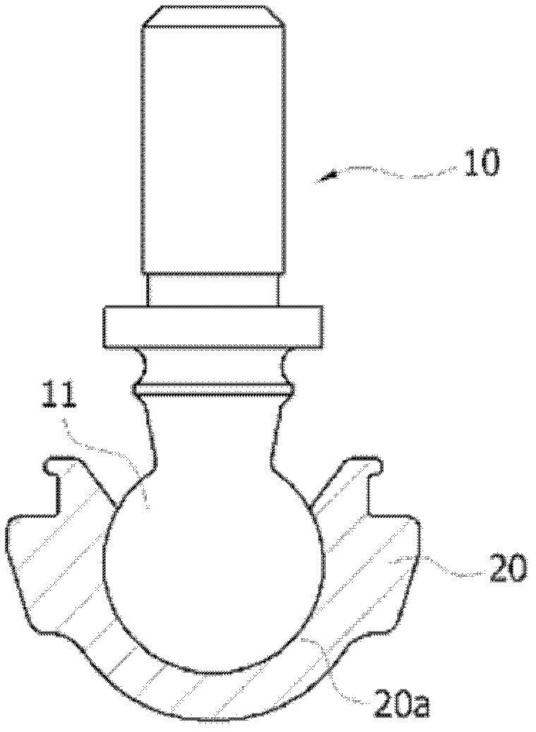
[0032] The present invention consists of the following parts: an upper mold 100, inside which is formed a shape for injection molding a ball seat 20 of synthetic resin material, which surrounds the outside of the spherical head 11 of the ball stud 10; a lower mold 200, which It is arranged at the lower part of the above-mentioned upper mold 100, forming a molding surface for forming a part of the above-mentioned ball seat 20; a fixing fixture 300, which is used to fix the above-mentioned ball stud 10 to the molding position of the above-mentioned upper mold 100 and the lower mold 200; A rotating component (not shown) is used to rotate the above-mentioned...


PUM


Abstract

It is an aim of the present invention to provide an apparatus and a method for manufacturing a ball joint which can reduce torque generated between a ball stud and a ball seat. For this purpose, the present invention comprises an upper mold, the interior of which is shaped for injection-molding a ball seat made of synthetic resin materials and covers an outer surface of a spherical head portion of the ball stud; a lower mold which is arranged below the upper mold and which has a molding surface for forming a portion of the ball seat; a fixing jig for fixing the ball stud at the molding location of the upper mold and the lower mold; and a rotating member for rotating the fixing jig.

Description

technical field [0001] The present invention relates to a ball joint manufacturing device and manufacturing method, and more specifically, to a ball joint manufacturing device and manufacturing method capable of reducing the rotational torque of the ball joint. Background technique [0002] In general, many shocks are applied to the wheels of a car depending on the state of the road surface, so a suspension device is provided which buffers the shocks so as to prevent the shocks from being directly transmitted to the vehicle body. [0003] A ball joint is a device that can be rotated and tilted in any plane, and is usually used in the steering or suspension system of a car. [0004] This ball joint is composed of the following structure: the spherical head of the ball stud is inserted inside the ball seat so that it can rotate and tilt, the above ball seat is fixed by the shell, and the dust cover is fixed between the shell and the ball. Between the ends of the seats. [00...

Claims


Application Information

Patent Timeline
Patent Type & Authority Applications(China)
IPC IPC(8): B29C45/14F16C11/06
CPCB29L2031/04B29C45/14754F16C11/0657B29C45/14F16C11/06
Inventor 金盛錄
Owner CENTRAL
Why Eureka
Try Eureka