Ultrasonic imaging with a variable refractive lens

A refractive index, ultrasound image technology, used in the use of re-radiation, sound-producing instruments, and the re-radiation of sound waves

Inactive Publication Date: 2012-01-18
KONINK PHILIPS ELECTRONICS NV
View PDF4 Cites 8 Cited by
  • Summary
  • Abstract
  • Description
  • Claims
  • Application Information

AI Technical Summary

Problems solved by technology

In particular, it can be seen as an object of the present invention to provide a method for generating ultrasound images using a variable refractive index lens which solves the problems of the prior art requiring relatively small transducers for high frequency ultrasound applications. above question

Method used


Image

  • Ultrasonic imaging with a variable refractive lens
  • Ultrasonic imaging with a variable refractive lens
  • Ultrasonic imaging with a variable refractive lens

Examples


Embodiment Construction

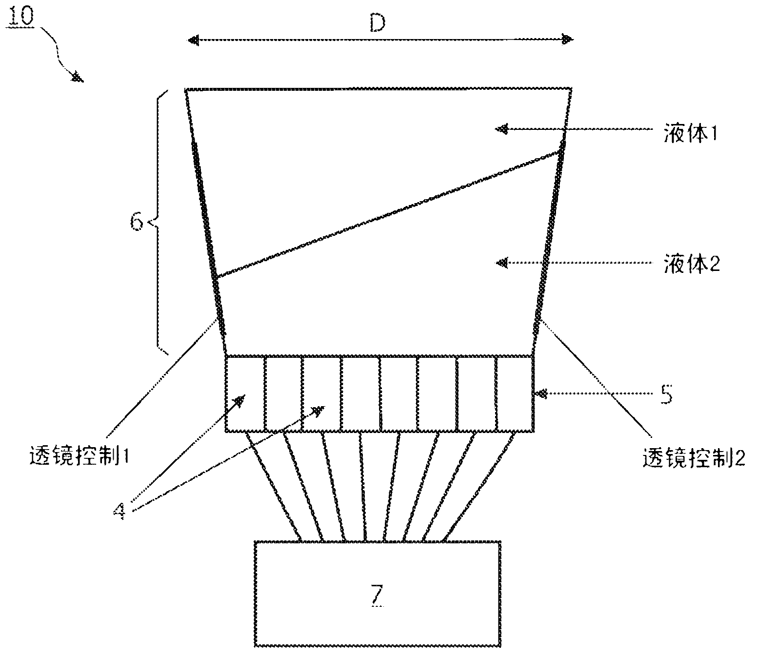
[0053] figure 1 is a schematic diagram of an imaging system 10 with a variable index lens 6 having a fluid 1 and a fluid 2 . In this embodiment, the electrowetting lens and further details and references thereto can be found in WO 20047051323 and WO 2008 / 0 / 4455 entitled "Apparatus for forming Variable Fluid Meniscus Configurations", belonging to the same applicant. Both references are hereby incorporated by reference in their entirety. The lens 6 has the appropriate voltage control indicated on the side of the lens 6 .

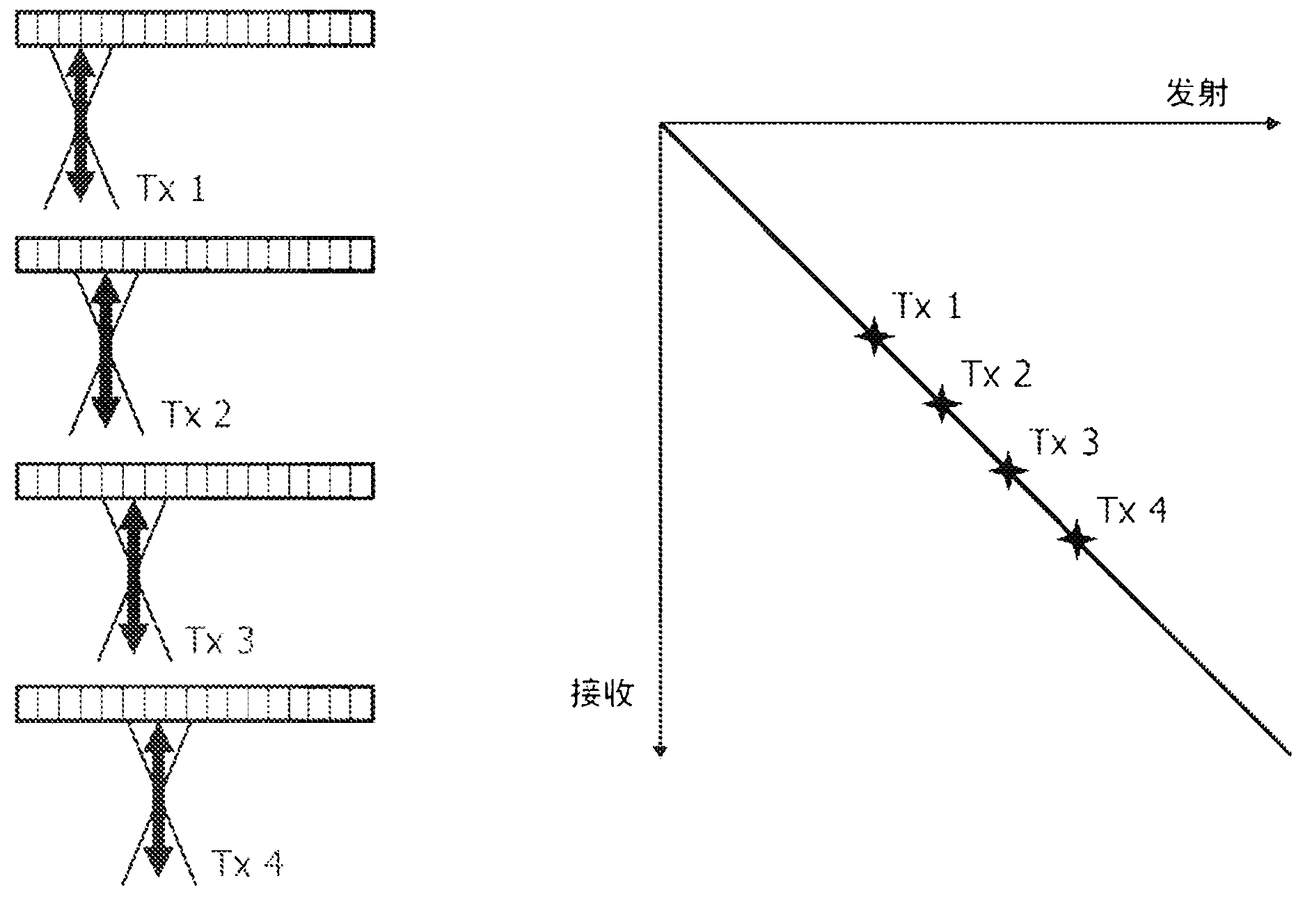
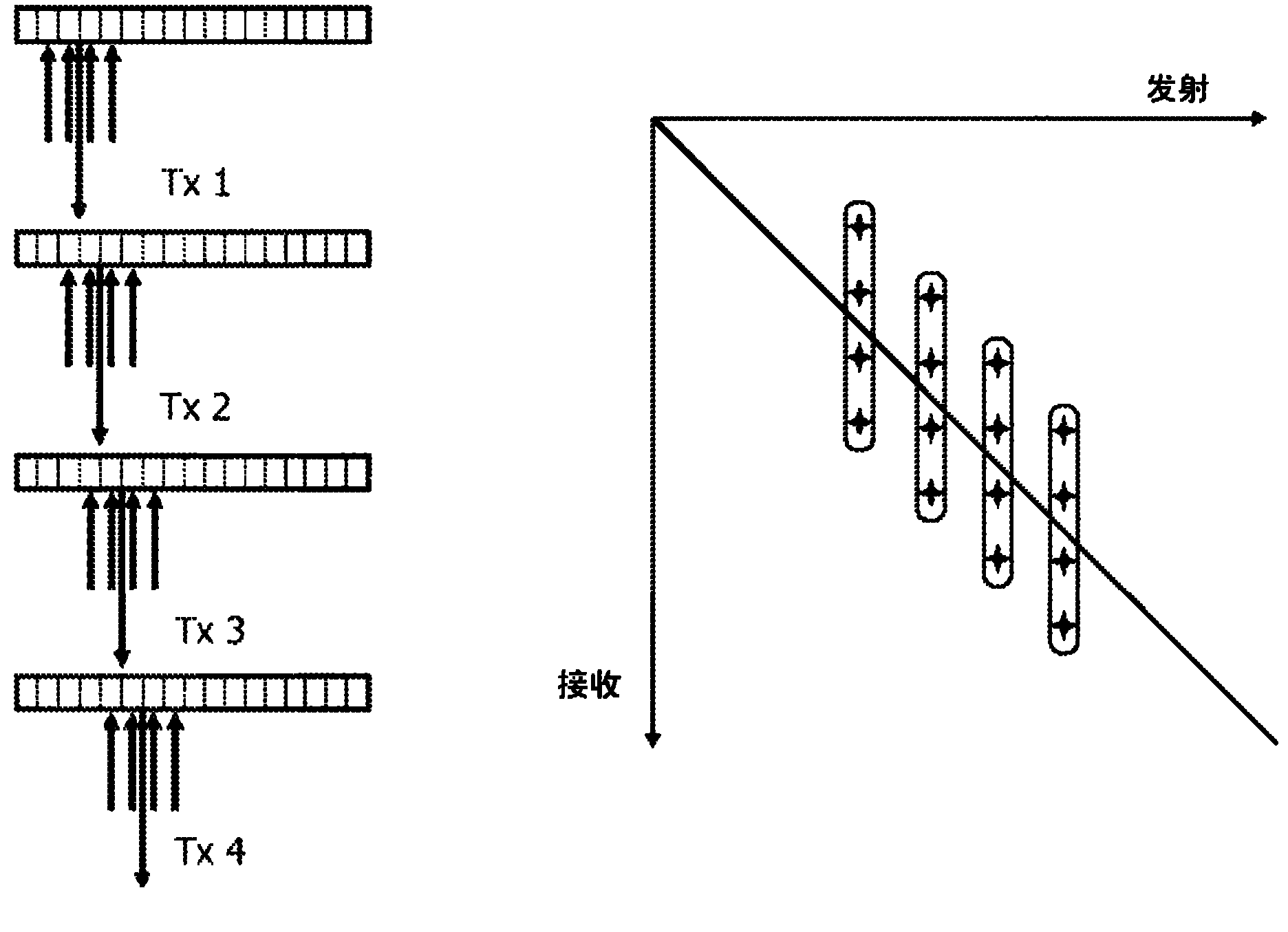
[0054] Below the lens 6 is placed an array 5 of transducers 4 . The lens 6 is used for rough manipulation. It steers the transmit beam and keeps pointing in the same direction during reception. Echoes from on-axis (and from receive focal depth) are well aligned throughout the multi-element array. The signals on the array elements are received by a multi-channel receive beamformer 7 . The beamformer is typically a data sampling beamformer. By changing th...


PUM


Abstract

The present invention relates to a method for producing an ultrasound image with a variable refractive lens (6) by transmitting a plurality of transmit beams (Txl-Tx4) from an array of transducers (5) and receiving echo signals with the array of transducers (5) through the variable refractive lens (6) with an associated lens shape. By combining echo signals of receive lines from different transmit beams which are spatially related, the invention enable producing an image using image data. The invention is beneficial for high frequency ultrasonic imaging with the transducers being relatively larger sized than hitherto needed for high frequency applications. The array of transducers does not need to be 'well- sampled'; i.e. having the width or size being comparably to the center wavelength of the ultrasonic signals to be received. This is particularly important at very high frequencies where well- sampled arrays would require very small elements that would be very challenging to manufacture.

Description

technical field [0001] The present invention relates to a method for generating ultrasound images using a variable refractive index lens. [0002] The invention also relates to an imaging system comprising a variable refractive index lens arranged to produce an ultrasound image, and a computer program product adapted to enable a computer system to control such an imaging system, the computer system comprising a At least one computer for the data storage device. Background technique [0003] Conventional ultrasound is performed by using an array of elements to focus and steer an ultrasound beam in a pulse-echo fashion. Beams are formed by delaying and summing the signals received by the array. Multiple receive beams can be formed for a single transmit event by imposing different delays on the same receive data. Today's systems typically use 2 or 4 receive beams (or lines) to increase the frame rate. [0004] Fluid focusing techniques have been proposed for ultrasound imag...

Claims


Application Information

Patent Timeline
Patent Type & Authority Applications(China)
IPC IPC(8): G01S7/52G01S15/89G10K11/30
CPCG01S15/8956G01S7/52095G01S7/5209G10K11/30G01S15/8909G01S7/52028
Inventor M·R·伯切Y·S·史J·罗贝尔
Owner KONINK PHILIPS ELECTRONICS NV
Why Eureka
Try Eureka