Chamfering die

A chamfering die and chamfering technology, applied in the field of cold stamping dies, can solve problems such as time-consuming product surface, scratches and burrs, and achieve the effects of improving production efficiency, precise dimensional processing, and ensuring product quality

Inactive Publication Date: 2012-01-25
SUZHOU RISING CREATION PRECISION TOOLS
View PDF0 Cites 14 Cited by
  • Summary
  • Abstract
  • Description
  • Claims
  • Application Information

AI Technical Summary

Problems solved by technology

[0004] In the production process of various existing terminal products, step-by-step thinning of stamping parts is often used to produce chamfe

Method used


Image

  • Chamfering die
  • Chamfering die
  • Chamfering die

Examples


Embodiment Construction

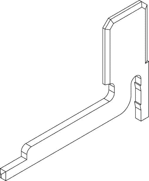
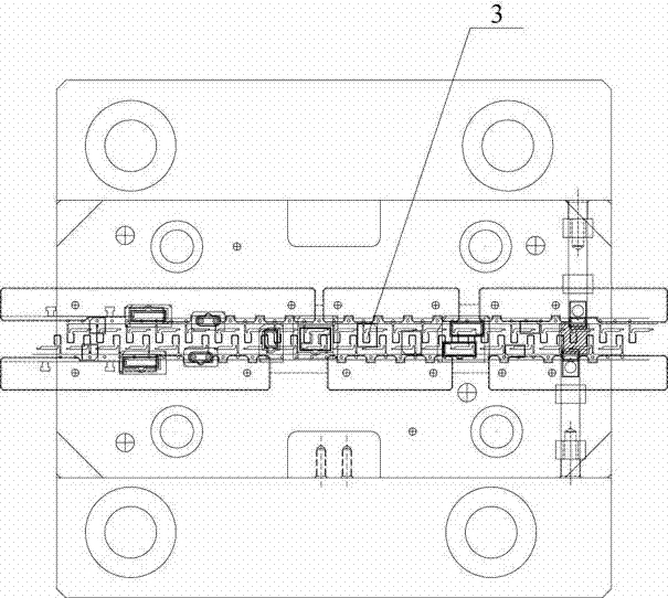
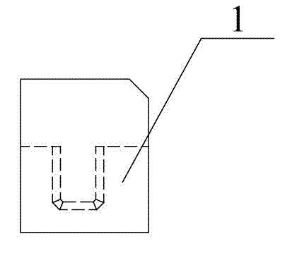
[0019] combine Figure 1 to Figure 6 Describe a kind of chamfering die of the present invention, it comprises the punch and die that match, and punch and die have chamfering upper die 1 and chamfering lower die 2 corresponding to the shape of product chamfering part. The longitudinal sections of the chamfering upper die 1 and the chamfering lower die 2 are straight chamfering or round chamfering. Wherein, the punch is fixedly connected sequentially from top to bottom by the upper die base, the upper backing plate and the chamfering upper die 1 . Die is fixedly connected successively from top to bottom by chamfering lower die 2, lower backing plate, lower die holder and die foot. The chamfering upper die 1 and the chamfering lower die 2 correspond to the shape of the chamfering part of the terminal 3, and both the punch and the die are installed on the punching machine.

[0020] The blank to be processed is located between the punch and the die of the chamfering die, the punc...


PUM


Abstract

The invention discloses a chamfering die and relates to a cold stamping die. The chamfering die is designed for solving the problems the step-by-step thinning stamping is mostly adopted for generating chamfer angels against the current various terminal products during the production process, the manual operation is time-consuming and a chamfering machine can easily produce phenomena of scratches and burrs on the surfaces of the products. The chamfering die comprises a male die and a female die which are matched, and the male die and the female die have a chamfering upper die and a chamfering lower die which correspond to the shape of chamfer angle parts of the products. The chamfering die is particularly suitable for die-pressing production of metal parts with chamfer angles at the end parts.

Description

technical field [0001] The invention relates to a cold stamping die, in particular to a chamfering die. Background technique [0002] The terminal block refers to the terminal block, and the types include single hole, double hole, socket, hook, etc., and the material classification includes copper-plated silver, copper-plated galvanized, copper, aluminum, iron, etc. For example, the liquid crystal display (LCD) terminal is an important part to connect the LCD, through which it is connected with the display screen to realize the transmission of electrical signals. Similarly, the battery terminals in a notebook also serve as an electrical connection. The various terminals mentioned above are mostly metal stamping parts with chamfered end faces. [0003] At present, in the process of producing battery terminals and other products, most enterprises use chamfering machines to thin the right-angled edges of stamping parts step by step to produce chamfers. Scratches and burrs se...

Claims


Application Information

Patent Timeline
IPC IPC(8): B21D28/14
Inventor 余桂萍
Owner SUZHOU RISING CREATION PRECISION TOOLS
Why Eureka
Try Eureka