Spiral-flow type motor vehicle venting spark quencher

A spark arrester, motor vehicle technology, applied in exhaust devices, machines/engines, mechanical equipment, etc., can solve problems such as poor reliability, low separation and capture efficiency, fire, etc., to achieve stable and reliable performance, flexible configuration, The effect of improving efficiency

Inactive Publication Date: 2013-04-03
寇志鹏 +1
View PDF5 Cites 0 Cited by
  • Summary
  • Abstract
  • Description
  • Claims
  • Application Information

AI Technical Summary

Problems solved by technology

[0004] For a long time, the valve-type motor vehicle exhaust spark extinguisher has been known in common use. It is characterized in that it is composed of a shroud and a valve core, and the spark particles in the exhaust are separated and captured by a double-layer filter or a single-layer filter. When the exhaust gas passes through, the flow direction of the exhaust gas is at right angles to the plane of the filter screen; its disadvantage is that the separation and capture of spark particles in the exhaust gas is separated and captured by a single filter screen, and there is a defect that the separation and capture efficiency is not high ; When the motor vehicle exhaust is filtered by the valve-type spark extinguisher, there may still be sporadic spark particles discharged, which may cause fire and explosion accidents
[0006] This utility model cites the concept of swirling flow for the first time, which is a useful exploration of the swirling flow spark extinguishing device, but the disadvantages are: 1. Its structural features cannot effectively generate swirling flow, and the exhaust flow cannot separate and trap spark particles. 2. The deflector makes the air flow rotate when it is discharged, and the spark particles are rotated and discharged together, and the spark particles cannot be separated and captured; 3. The high temperature and particle-containing exhaust push multiple moving parts to rotate, and the reliability is poor
[0007] It can be seen that although this technical solution refers to the concept of swirl flow, it does not produce the function of separation and capture of spark particles by swirl flow. The essential feature of its separation and capture method is still the traditional filter separation and capture

Method used


Image

  • Spiral-flow type motor vehicle venting spark quencher
  • Spiral-flow type motor vehicle venting spark quencher
  • Spiral-flow type motor vehicle venting spark quencher

Examples


Embodiment Construction

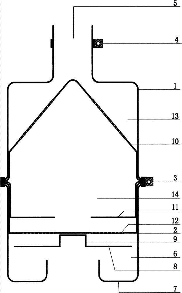
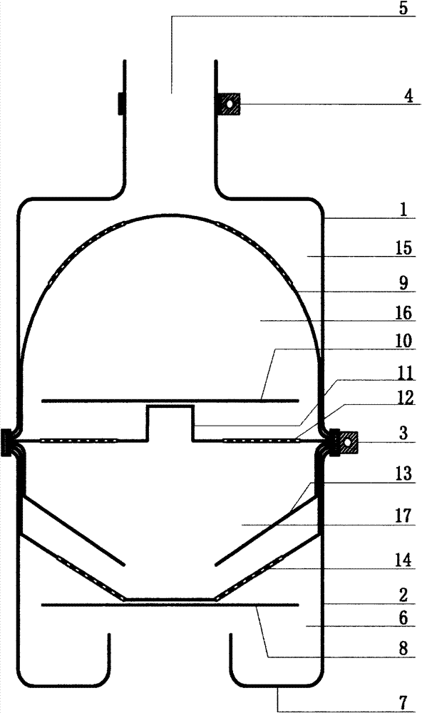
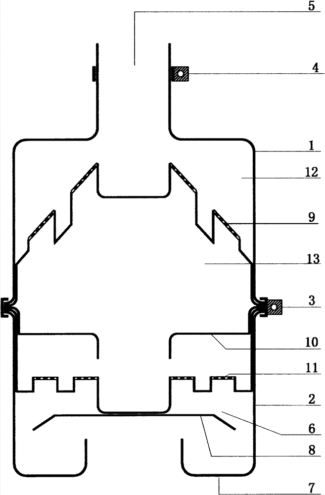
[0024] There are two kinds of substances in the engine exhaust, among which the combustion exhaust gas is gas, and the spark particles are solid, so the engine exhaust is a gas-solid flow. In the gas-solid flow, the density of the spark particles is greater than that of the combustion exhaust gas, so the inertial centrifugal force of the spark particles is greater than that of the combustion exhaust gas.

[0025]In this swirling spark extinguisher, when the gas-solid flow rotates instantaneously around a certain central axis, the inertial centrifugal force causes the spark particles and the combustion exhaust gas to move relative to each other and fly away from the center, so the spark particles and the combustion exhaust gas The flow direction is separated; the separated combustion exhaust gas is discharged through the filter hole and the exhaust hole, while the spark particles flying away from the center are thrown to the filter wall and the turbulent flow chamber; the spark ...


PUM


Abstract

The invention relates to a spiral-flow type motor vehicle venting spark quencher which discloses an engine venting processing device used for quenching sparks, and provides a spiral-flow type spark quencher combining spiral-flow centrifugal separation trapping and filter screen obstruction separation trapping. A flow guidance cover and a valve plug are assembled to form a flow guidance chamber, aspiral-flow chamber and a spiral-flow exhaust chamber; an anaerobic spiral-flow chamber and an anaerobic turbulence cavity are formed when exhausted gas passes through; and spark particles are subjected to multistage compound separation trapping quenching combining the spiral-flow centrifugal separation trapping and the filter screen obstruction separation trapping. The spiral-flow type motor vehicle venting spark quencher is suitable for guaranteeing the driving safety of a motor vehicle in the flammable and combustible environment, and fire hazards and explosions can be avoided.

Description

1. Technical field: [0001] The invention relates to an engine exhaust treatment device for spark elimination, in particular to a motor vehicle exhaust spark extinguishing device applied to fire prevention and explosion prevention in an inflammable and explosive environment. 2. Technical background: [0002] After the motor vehicle engine is started, there will be sparks in the exhaust. When the motor vehicle travels to an inflammable and explosive environment, the sparks will cause fire and explosion accidents. [0003] The motor vehicle exhaust spark extinguisher is a device installed at the port of the motor vehicle engine exhaust pipe to discharge the combustion exhaust gas from the engine, and the spark particles are separated, captured and extinguished. The equipment that must be installed plays an important role in ensuring the safety of motor vehicles in flammable and explosive environments and avoiding fire and explosion accidents. [0004] For a long time, the valv...

Claims


Application Information

Patent Timeline
Patent Type & Authority Patents(China)
IPC IPC(8): F01N3/06
Inventor 寇志鹏寇卫东
Owner 寇志鹏
Why Eureka
Try Eureka