Infrared remote control receiving circuit

A receiving circuit, infrared remote control technology, applied in non-electrical signal transmission systems, signal transmission systems, instruments, etc., can solve the problems of reduced gain, no correct signal output at the output end, unsuitable for infrared transmission of data signals, etc., reaching the chip area The effect of small, good sensitivity, good noise suppression performance

Active Publication Date: 2012-01-25
HANGZHOU SILAN OPTRONICS
View PDF3 Cites 4 Cited by
  • Summary
  • Abstract
  • Description
  • Claims
  • Application Information

AI Technical Summary

Problems solved by technology

In the initial stage, a normal waveform can also be obtained at the output terminal of the output module; but as Vctrl accumulates and rises, the gain continues to decrease, and after a period of time, the output terminal of the output module does not have the correct signal output
Therefore, traditional technology is not suitable for infrared transmission of data signals

Method used


Image

  • Infrared remote control receiving circuit
  • Infrared remote control receiving circuit
  • Infrared remote control receiving circuit

Examples


Embodiment Construction

[0060] The content of the present invention will be further described below in conjunction with the accompanying drawings and embodiments.

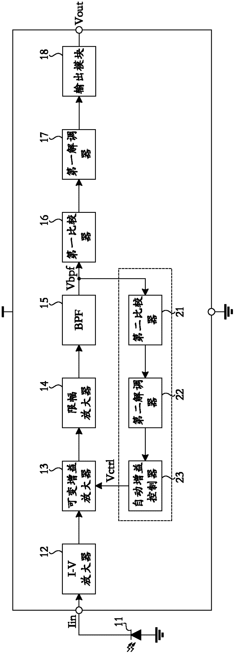
[0061] Such as Figure 7 As shown, the infrared receiving remote control circuit of the present embodiment includes:

[0062] An I-V amplifier 52 converts the current signal Iin received by the infrared remote controller into a voltage signal; the current signal Iin is converted from the light signal by the photodiode 51;

[0063] A variable gain limiting amplifier 53 receives the output of the I-V amplifier 52 and adjusts the gain of the I-V amplifier 52 output;

[0064] A limiting amplifier 54, receiving the output of the variable gain amplifier 53 and amplifying it, limiting the maximum peak value of the output of the variable gain amplifier 53;

[0065] A band-pass filter (abbreviated as BPF) 55 carries out band-pass filtering to the output signal of the limiting amplifier 54, outputs the electrical signal Vbpf identical to the carr...


PUM


Abstract

The invention discloses an infrared remote control receiving circuit, which comprises a variable grain amplifier and a limiting amplifier, a band pass filter, a first comparator, a first demodulator, an output module, a second comparator, a second demodulator, an output time detector and a logic arithmetic unit, wherein the variable grain amplifier and the limiting amplifier are used for amplifying a voltage signal and controlling voltage gain; the band pass filter carries out band pass filtering on the output signal of the limiting amplifier; the first comparator compares the output signal of the band pass filter with a first preset potential; the first demodulator demodulates the output of the first comparator; the output module outputs the output of the first demodulator; the second comparator compares the output signal of the band pass filter with a second preset potential; the second demodulator demodulates the output of the second comparator; the output time detector detects whether the time the output of low-level pulse exceeds a preset time or not; the logic arithmetic unit calculates the outputs of the second demodulator, the output time detector and the first demodulator; and the gain of the variable grain amplifier is controlled by an automatic gain controller. The circuit is free from being limited by a signal duty ratio and signal duration when being used for transmitting data signal, and the gain can be correspondingly regulated according to the variation of environment noise.

Description

technical field [0001] The invention relates to an infrared remote control receiving circuit, in particular to an infrared remote control receiving circuit capable of realizing data transmission. Background technique [0002] The principle of infrared remote control transmitting signal is: the signal to be transmitted is modulated by high-frequency carrier, and then emitted by the infrared light-emitting tube on the remote control. The infrared light-emitting tube emits a series of carrier signals (marked as S1 signal, see figure 2 ) and does not transmit a carrier signal (marked as S0 signal, see figure 2 ) to realize the transmission of signal high and low levels. [0003] Such as figure 1 Shown is the traditional infrared remote control receiving circuit. The photodiode 11 receives the light signal and converts it into a weak electrical signal. After being amplified by multi-stage amplifiers such as I-V amplifier 12, variable gain amplifier 13, and limiting amplifier...

Claims


Application Information

Patent Timeline
Patent Type & Authority Applications(China)
IPC IPC(8): G08C23/04
Inventor 李昕华杜庆丰芦祥
Owner HANGZHOU SILAN OPTRONICS
Why Eureka
Try Eureka