AI technical title is built by PatSnap AI team. It summarizes the technical point description of the patent document.
A technology for glucose, optical measurement, used in sensors, medical science, diagnostic recording/measurement, etc., can solve problems such as hindering the exchange of cellular substances
Inactive Publication Date: 2012-01-25
GLUSENSE LTD
View PDF75 Cites 20 Cited by
Summary
Abstract
Description
Claims
Application Information
AI Technical Summary
This helps you quickly interpret patents by identifying the three key elements:
Problems solved by technology
Method used
Benefits of technology
Problems solved by technology
However, the overgrowth of fibrous tissue surrounding the implanted cells gradually hampers the exchange of substances between the cells and their environment
Method used
Image
Click on the blue label to locate the original text in one second.
Reading with bidirectional positioning of images and text.
Examples
Embodiment Construction
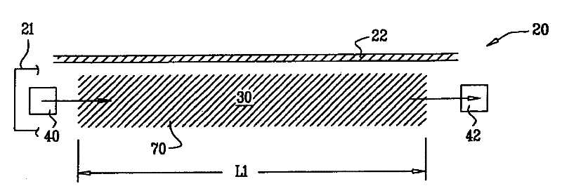
[0354] now refer to figure 1 , figure 1 is a schematic diagram of an optical measurement device 20 including an electromagnetic light source 40 and a detection system 42, according to some applications of the invention. Typically, the light source 40 is used to emit electromagnetic radiation in the visible range or the infrared range. Optical measurement device 20 is used to detect and measure the concentration of an analyte, such as glucose, in the interstitial fluid of a subject. (In the context of this specification, the example of glucose as an analyte is by way of illustration and not limitation.) Typically, device 20 is intended to be implanted subcutaneously under the skin 22 of a subject and includes a support 21 (e.g., a housing , brackets or glue). Sampling zone 30 is disposed within the area defined by support 21 of device 20, generally between light source 40 and detection system 42 (as shown). Support 21 is configured to help form the proper spatial relationsh...
PUM
Abstract
Apparatus is provided, including a support (21) configured to be implanted within a body of a subject and a sampling region (30, 1430) coupled to the support (21). The apparatus is configured to passively allow passage through the sampling region (30, 1430) of at least a portion of fluid from the subject. The apparatus also includes an optical measuring device in optical communication with the sampling region (30, 1430). The optical measuring device comprises at least one light source (40) configured to transmit light through at least a portion of the fluid, and at least one sensor (42) configured to measure a parameter of the fluid by detecting light passing through the fluid. Other applications are also described.
Description
[0001] Cross References to Related Applications [0002] This application: [0003] (a) is a continuation-in-part of U.S. Patent Application 12 / 344,103, filed December 24, 2008, to Gross et al., entitled "Implantable optical glucose sensing," and claims priority thereto; [0004] (b) claiming priority to U.S. Provisional Patent Application 61 / 149,110, filed February 2, 2009, to Gil et al., entitled "Compact optical sensor for flat fluorescent sample regions"; and [0005] (c) involves: [0006] U.S. Provisional Patent Application 60 / 588,211 to Gross et al., entitled "Implantable sensor," filed July 14, 2004; [0007] U.S. Provisional Patent Application 60 / 658,716 to Gross et al., entitled "Implantable fuel cell," filed March 3, 2005; [0008] PCT patent application PCT / IL2005 / 000743 entitled "Implantable power sources and sensors" filed on July 13, 2005, to Gross et al.; [0009] U.S. Provisional Patent Application 60 / 786,532 to Gross et al., entitled "Implantable sensor," f...
Claims
Application Information
Patent Timeline
Application Date:The date an application was filed.
Publication Date:The date a patent or application was officially published.
First Publication Date:The earliest publication date of a patent with the same application number.
Issue Date:Publication date of the patent grant document.
PCT Entry Date:The Entry date of PCT National Phase.
Estimated Expiry Date:The statutory expiry date of a patent right according to the Patent Law, and it is the longest term of protection that the patent right can achieve without the termination of the patent right due to other reasons(Term extension factor has been taken into account ).
Invalid Date:Actual expiry date is based on effective date or publication date of legal transaction data of invalid patent.

