Method and system for performing swept-wavelength measurements within an optical system

a technology of optical system and swept wavelength, applied in the field of methods, can solve the problems of difficult or impossible to stably achieve, limited use of optical feedback loop, and inability to use optical feedback loops in optical measurement systems,

Inactive Publication Date: 2004-08-17
XYRATEX CORP
View PDF8 Cites 108 Cited by
  • Summary
  • Abstract
  • Description
  • Claims
  • Application Information

AI Technical Summary

Problems solved by technology

Optical measurement systems, optical storage and retrieval systems and other optical systems may be limited by many factors, including illumination beam size, diffraction limit, detector noise, and resolution.
However, in certain applications it may not be practical to use such a feedback loop, especially when the control mechanism is the illumination wavelength, as the wavelength must be controlled very precisely for resonators having substantial path length (necessary for resonators having a high Q-factor).
With a resonator length of 1000.lambda., phase control to 0.1% of the wavelength dictates control of the illumination wavelength to within 1 part per million, which is difficult or impossible to stably achieve while maintaining high speed operation by using a tunable illumination source and feedback loop.

Method used


Image

  • Method and system for performing swept-wavelength measurements within an optical system
  • Method and system for performing swept-wavelength measurements within an optical system
  • Method and system for performing swept-wavelength measurements within an optical system

Examples


Embodiment Construction

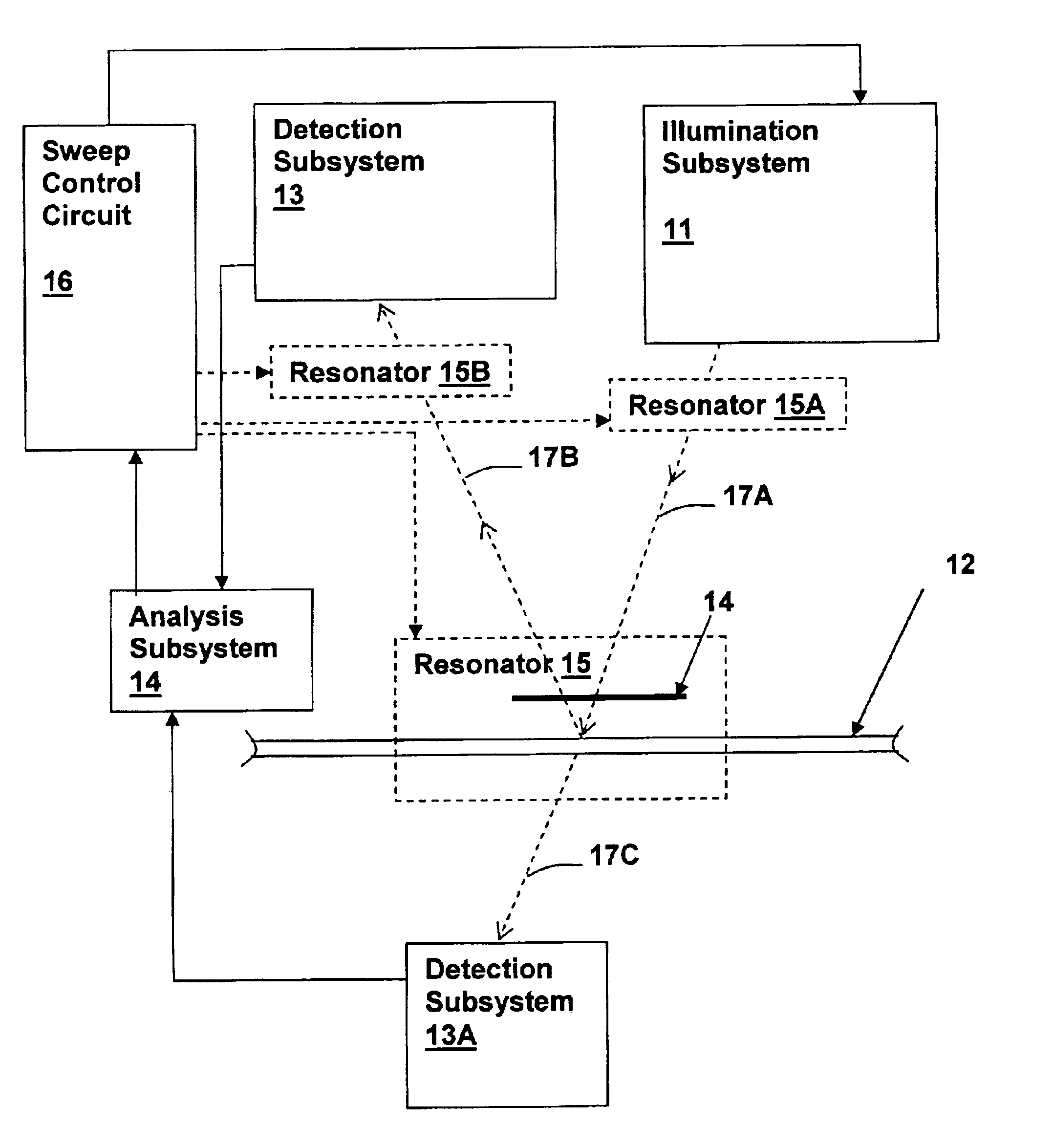
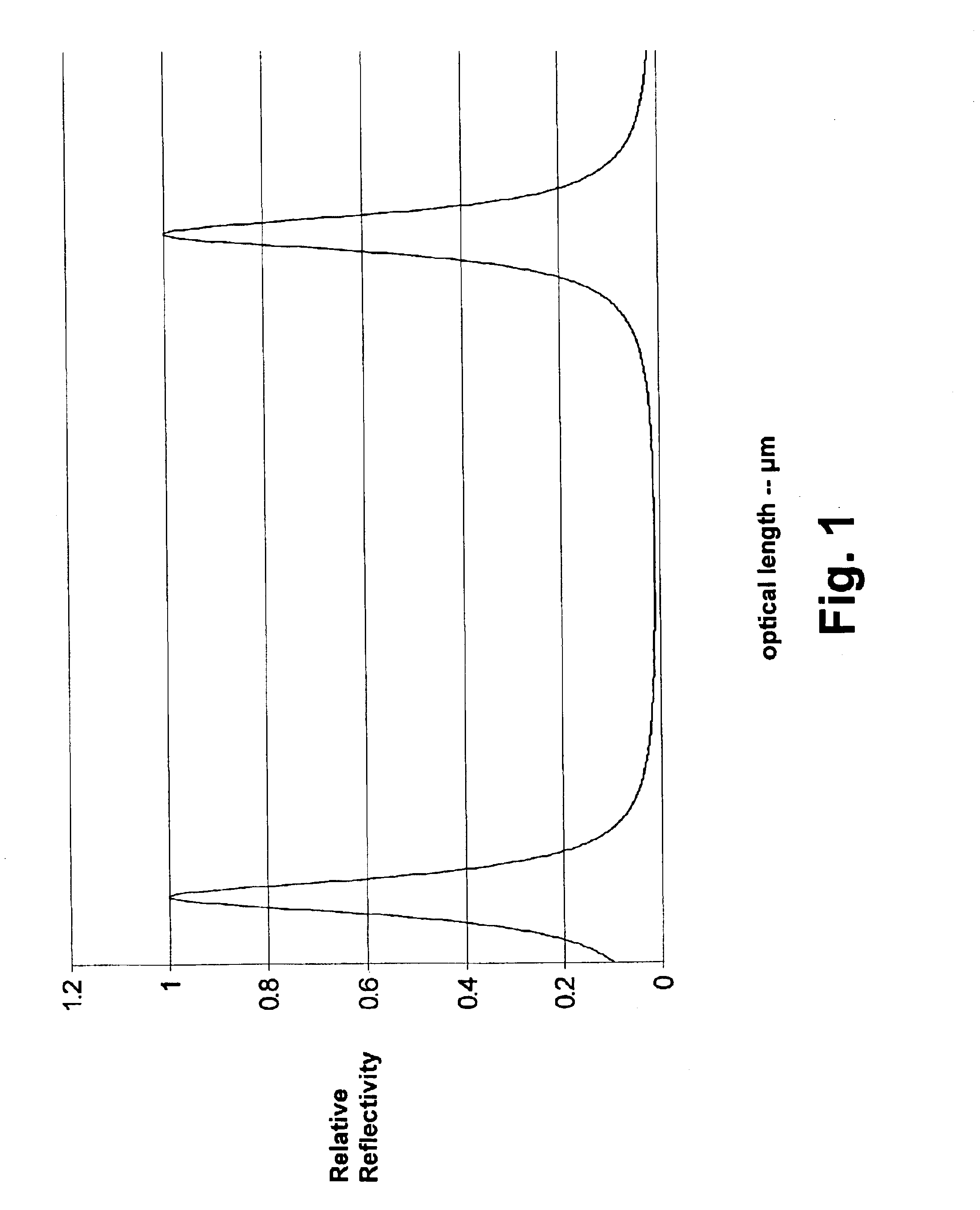
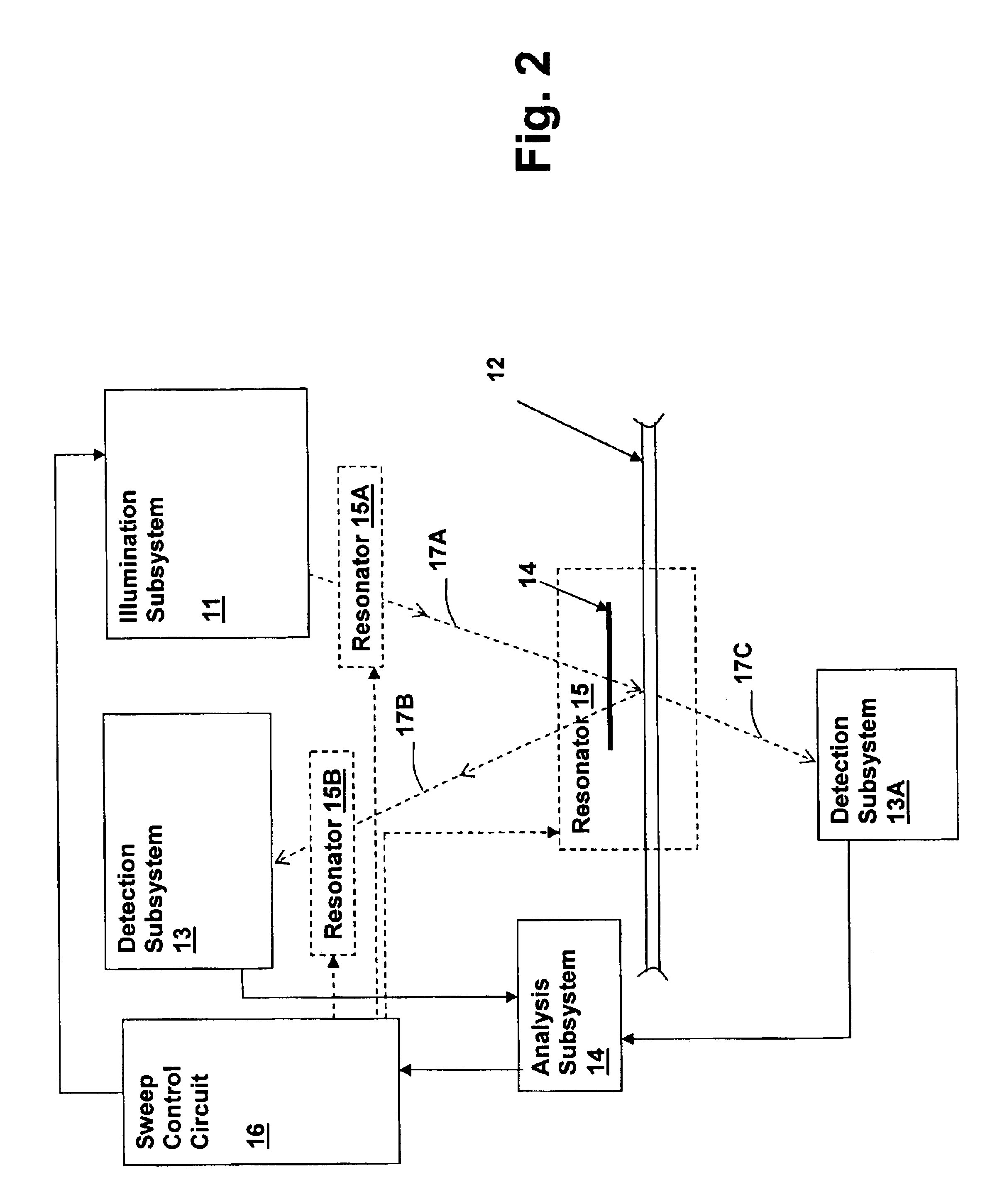
The above-incorporated patent applications describe various resonator-enhanced optical systems, such as optical storage data and retrieval systems having improved data density, illumination sources having narrowed beam widths and optical measurement systems having improved resolution and contrast and having improved detector phase / amplitude slope characteristics controlled over portions of the detector response. The above-recited improvements are developed by placement and tuning of resonators within the optical paths of the associated systems, in order to optimize the operating point on the resonator response function.

While the incorporation of a resonator improves the performance of the systems described within the above-incorporated patent applications, the resonator generally must be tuned precisely to a specific point in the response function. The tuning requirement is made even more stringent when the resonator operating point is set slightly off of resonance, producing improv...


PUM

PropertyMeasurementUnit
time domain analysisaaaaaaaaaa
optical characteristicsaaaaaaaaaa
optical lengthaaaaaaaaaa

Abstract

A method and system for performing swept-wavelength measurements within an optical system provides improved operation in resonator-enhanced optical measurement and data storage and retrieval systems. The system includes an illumination subsystem having a swept-wavelength mode, a detection subsystem, an interferometer or an optical resonator interposed in an optical path between the illumination subsystem and the detection subsystem and a time domain analysis subsystem. Multiple resonance points of the optical resonator are detected by the time-domain subsystem when the illumination subsystem is in the swept-wavelength mode in order to determine resonator or interferometer characteristic changes. The resulting information can be used directly as a measurement output, or cavity length information may also be used to adjust the operating wavelength of a constant wavelength mode of the illumination subsystem.

Description

1. Field of the InventionThis invention relates to optical systems, and more specifically, to optical systems that incorporating a coherent interference in either the illumination path or a measurement path.2. Description of the Related ArtOptical measurement systems, optical storage and retrieval systems and other optical systems may be limited by many factors, including illumination beam size, diffraction limit, detector noise, and resolution. The above-incorporated patent applications disclose techniques for enhancing the performance of a variety of optical systems and improving the resolution and sensitivity of optical technologies disclosed therein.It would be further desirable to improve the performance of the systems disclosed in the above-referenced patent applications, as well as other optical systems, in order to further improve their performance. The above-referenced patent application "METHOD AND SYSTEM FOR CONTROLLING RESONANCE WITHIN A RESONATOR-ENHANCED OPTICAL SYSTEM...

Claims


Application Information

Patent Timeline
Patent Type & Authority Patents(United States)
IPC IPC(8): G01N21/39G01N21/31G02B26/00G01J3/42G01J3/433
CPCG01J3/4338G01N21/39G02B26/001
Inventor CLARK, BRYAN
Owner XYRATEX CORP
Why Eureka
Try Eureka