Method and device for cleaning of engine exhaust gas

An engine, diesel engine technology, applied in mechanical equipment, engine components, combustion engines, etc., can solve problems such as small purification effects

Active Publication Date: 2012-01-25
MAN DIESEL & TURBO FILIAL AF MAN DIESEL & TURBO SE TYSKLAND
View PDF8 Cites 13 Cited by
  • Summary
  • Abstract
  • Description
  • Claims
  • Application Information

AI Technical Summary

Problems solved by technology

Therefore only a small puri

Method used


Image

  • Method and device for cleaning of engine exhaust gas
  • Method and device for cleaning of engine exhaust gas
  • Method and device for cleaning of engine exhaust gas

Examples


Embodiment Construction

[0021] The main field of application of the invention is large engines, in particular large two-stroke diesel engines, such as can be used, for example, as drives in ships or in stationary power plants or the like.

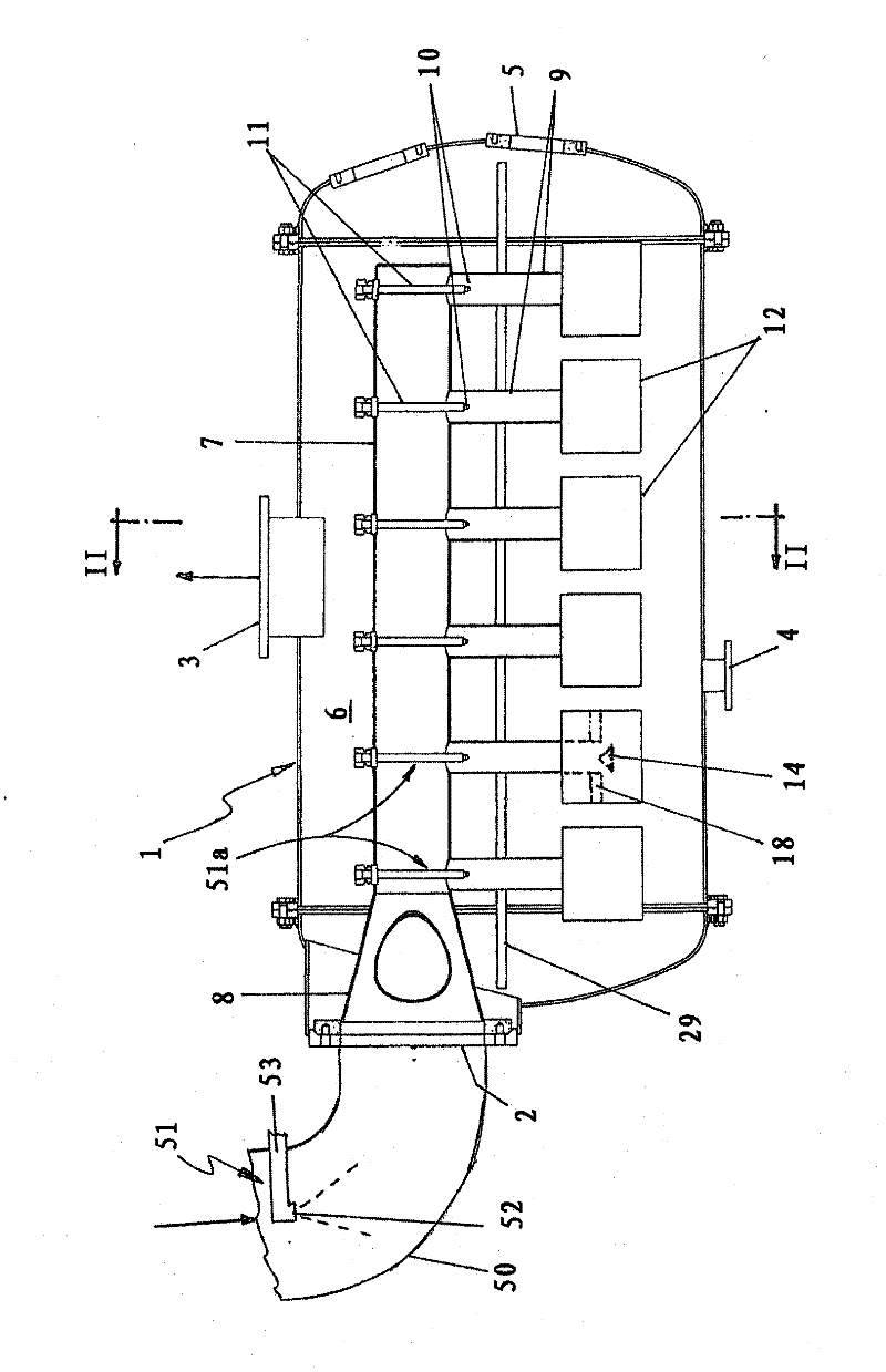
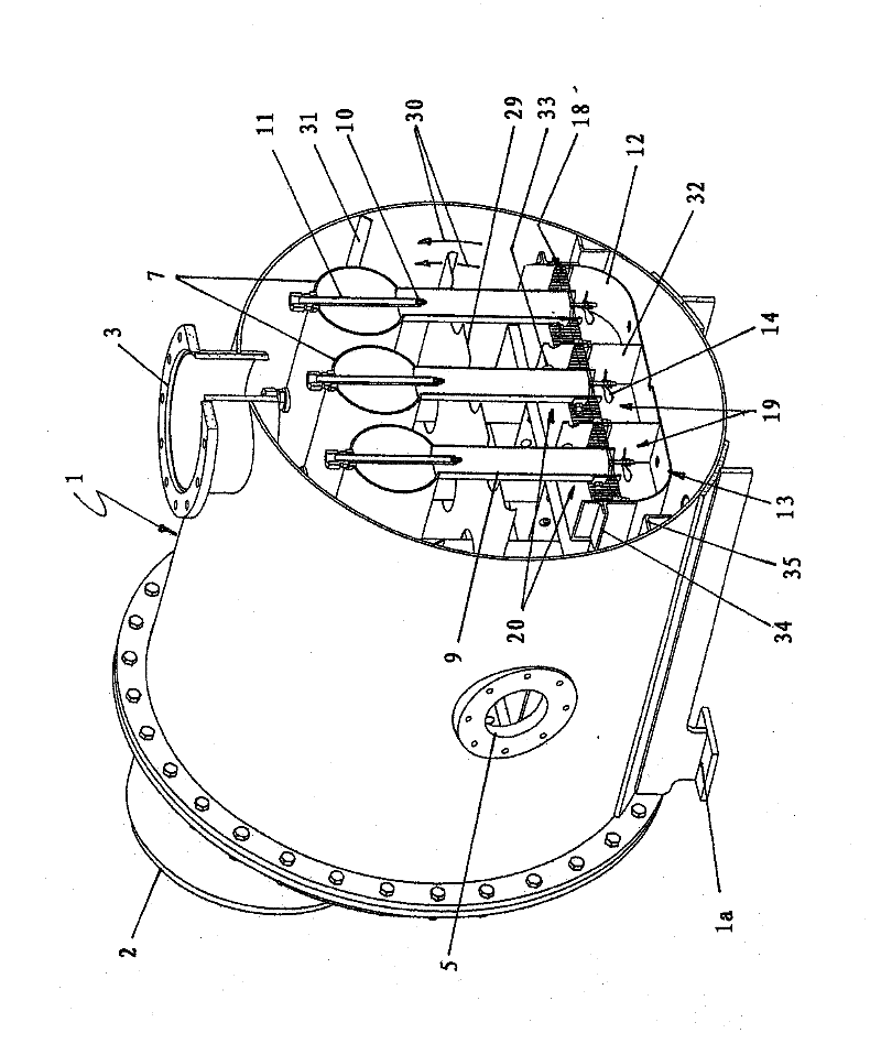
[0022] based on figure 1 and 2 The exhaust gas purification equipment of the present invention comprises a drum-shaped container 1, which is installed on a support 1a provided with feet. The container 1 has an exhaust gas inlet 2 arranged on the end side and an exhaust gas outlet 3 leading here upwards, and is provided below with a drain opening 4 . The exhaust gas inlet 2 is connected to an inlet line 50 which can be loaded with exhaust gas.

[0023] The drum-shaped container 1 comprises a cylindrical middle part which is closed by two caps which are flanged at the ends. The exhaust gas inlet 2 is arranged here in the upper region of an end-side cover. The exhaust gas outlet 3 is here approximately in the center of the dome region of the cylindrical middle pa...


PUM


Abstract

In cleaning engine exhaust gas, a high cleaning degree can be achieved by supplying at least a part of the finely dispersed cleaning liquid to be supplied to the exhaust gas to an exhaust gas total flow not yet split into partial flows. In said process, the exhaust gas is first brought into contact with a finely dispersed cleaning liquid, and the volume flow, formed from the exhaust gas and the finely dispersed cleaning liquid, subsequently has to pass a bath of cleaning liquid provided in a container (1), said bath being divided into a lower and an upper compartment (19, 20) by a gas- and liquid-permeable baffle element (18), wherein the volume flow, formed by exhaust gas and finely dispersed cleaning liquid, is introduced into the area of the cleaning liquid bath located underneath the baffle element (18), and from here,; runs through the area of the cleaning liquid bath located above the baffle element (18).

Description

technical field [0001] The present invention relates to a method and a device for purifying engine exhaust gases, in particular for use in a large engine, preferably a large two-stroke diesel engine. Background technique [0002] A method and a device for purifying exhaust gases in a motor vehicle engine are known from EP 1 230 969 A1. The exhaust gas to be cleaned is conducted by means of a perforated tube without pretreatment into an oil bath, above which a perforated cover is arranged as a splash guard. This results in a reduced contact time of the exhaust gas with the cleaning liquid formed here by the oil, which can have a detrimental effect on the absorption of impurities contained in the exhaust gas by the cleaning liquid. In this case they also generate relatively large gas bubbles in the oil bath, which come into contact with the cleaning liquid only at their surface but enclose a relatively large gas volume, thereby further aggravating the above-mentioned disadvan...

Claims


Application Information

Patent Timeline
IPC IPC(8): F01N3/04F01N3/037F02M25/07B01D47/02B01D47/06B01D47/10B01D53/78
CPCF01N3/04B01D53/77B01D47/06B01D47/02B01D53/92F01N3/037F01N2470/30F02M25/0718Y02T10/20B01D2258/012F01N2590/02B01D47/10Y02T10/121F02M26/15Y02T10/12
Inventor J·卡尔托弗特C·L·杰森M·L·泽伦森M·M·赫夫P·斯基约达格
Owner MAN DIESEL & TURBO FILIAL AF MAN DIESEL & TURBO SE TYSKLAND
Why Eureka
Try Eureka