
Winding machine

A technology of winding machine and yarn guide, which is applied in the direction of thin material processing, conveying filamentous materials, transportation and packaging, etc. It can solve problems such as jamming, easy function failure, skewing, etc., and achieve the effect of improving positioning accuracy

Active Publication Date: 2021-03-09
OERLIKON TEXTILE GMBH & CO KG
View PDF11 Cites 0 Cited by
  • Summary
  • Abstract
  • Description
  • Claims
  • Application Information

AI Technical Summary

Problems solved by technology

However, such inclined rails have a tendency to jam and skew the guides and are therefore prone to functional failure

Method used


Image

  • Winding machine
  • Winding machine
  • Winding machine

Examples


Embodiment Construction

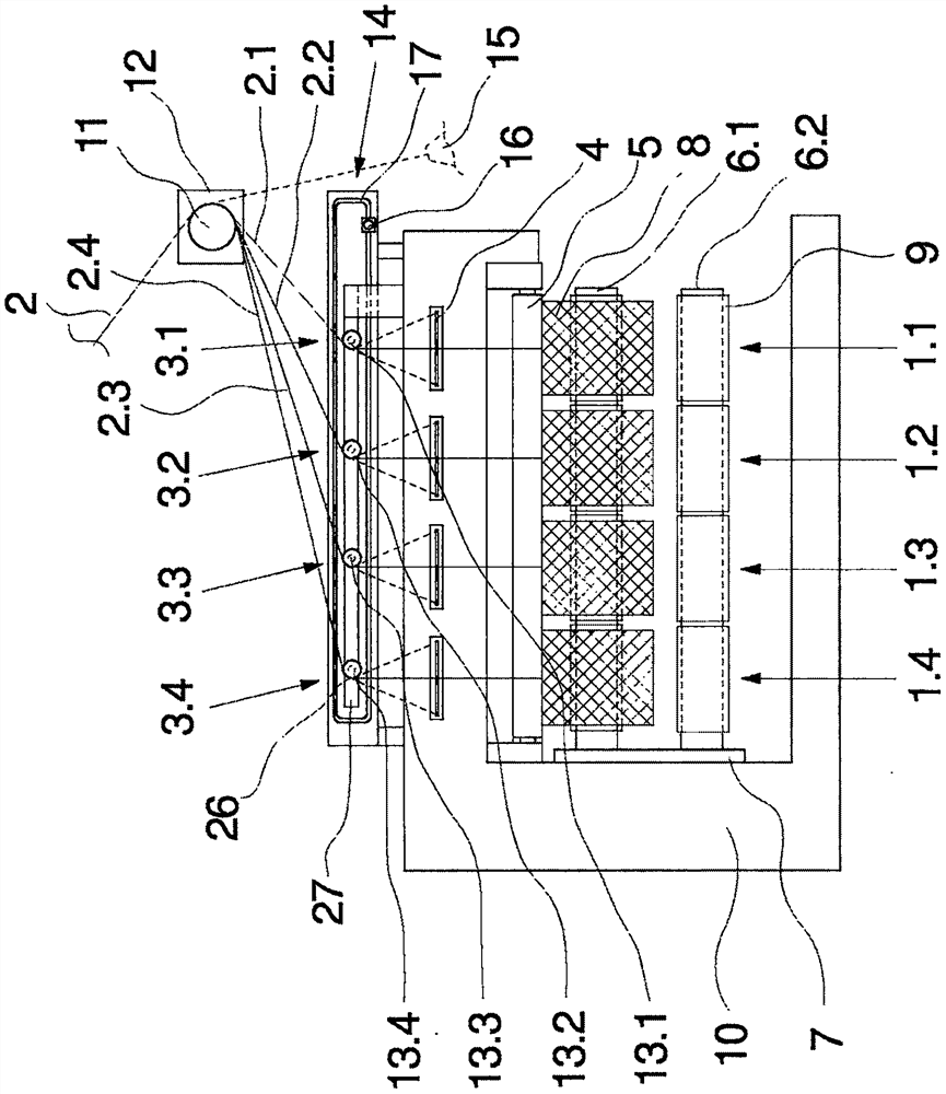
[0024] An embodiment of a winder according to the invention is figure 1 The side view is shown schematically. The winding machine according to the invention in this exemplary embodiment has four winding positions 1.1-1.4 which are arranged side by side in the machine frame. The winding stations 1.1-1.4 are arranged along the winding spindle 6.1 which is held in position in a protruding manner. One yarn of the yarn group 2 is supplied to each winding position 1.1-1.4 and wound into a bobbin 8 . The number of winding positions 1.1-1.4 and the number of threads 2.1-2.4 of the thread group 2 are exemplary here. In principle, such a winder can have up to 16 winding positions side by side.

[0025] The structure of these wrapping bits 1.1-1.4 is designed to be identical, so that the basic structure is described by one of the wrapping bits 1.1.

[0026] The winding station 1.1 has a traversing unit 4, whereby the supply yarn 2.1 is reciprocated in a traversing stroke. The traver...


PUM


Abstract

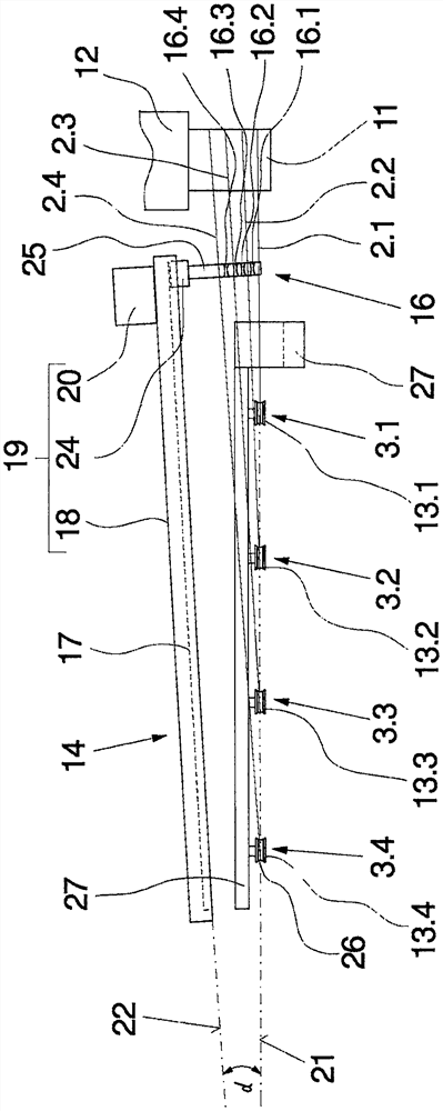
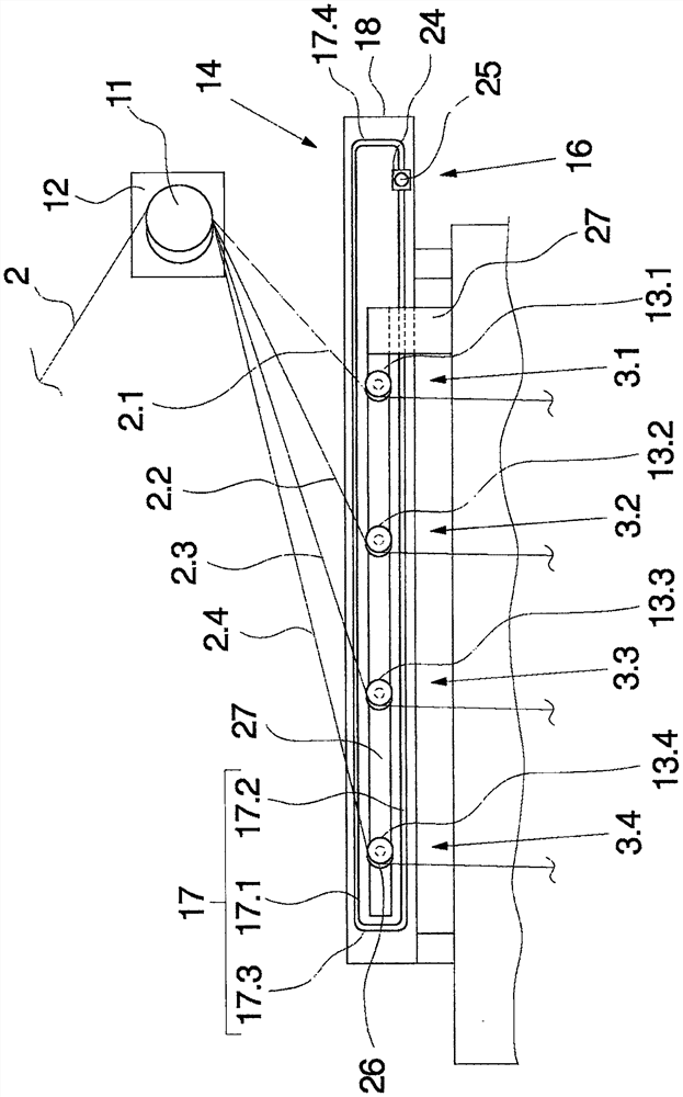
The invention relates to a winding machine for winding a plurality of yarns to form bobbins, which has a plurality of winding positions. The winding stations are arranged side by side along at least one winding spindle held in position in a protruding manner, wherein an overhead thread guide is arranged upstream of the winding stations in the yarn direction. The overhead yarn guide is associated with at least one yarn guide disk, which is arranged laterally of the winding station and aligned in the transverse direction of the winding spindle. For threading the yarn into the overhead thread guide at the start of the process, an auxiliary device is provided with a threading thread guide which has a plurality of guide grooves arranged side by side. The threading guide can be guided by means of a drive in a guide rail along the overhead thread guide which has at least one feed rail and one return rail. For safe guidance of the threading guide, the feed rail above the overhead thread guide and the return rail below the overhead thread guide are arranged according to the invention in vertically aligned guide planes of the threading guide, An angle in the range of 1° to 15° is formed between the guide plane of the threading thread guide and the alignment line of the overhead thread guide.

Description

technical field [0001] The invention relates to a winding machine for winding a plurality of yarns. Background technique [0002] The yarns produced in the form of yarn groups at the end of the melt spinning process are wound in parallel into bobbins. For this purpose, a winding machine is used which has a plurality of winding stations which are arranged along winding spindles held in position in a protruding manner on a machine frame. The winding spindle is used to receive the bobbins for simultaneous winding of said bobbins. The yarn laying takes place in so-called cross-winding, so that the yarns are individually reciprocated in the winding position by the traversing unit before being moved onto the package surface. The feeding into the winding position and the separation of the yarn groups takes place via a plurality of so-called overhead thread guides, which are each arranged upstream of the traversing unit in the winding position. The yarn group is usually supplied ...

Claims


Application Information

Patent Timeline
Patent Type & Authority Patents(China)
IPC IPC(8): B65H51/14B65H57/00B65H57/16B65H57/28B65H67/048
CPCB65H51/14B65H57/003B65H57/16B65H57/28B65H67/048B65H2701/3132
Inventor M·费希尔R·沃斯J·希佩尔M-A·赫尔恩多夫
Owner OERLIKON TEXTILE GMBH & CO KG
Learn More