
Mechanical and electric connection device for a coaxial cable conveying a high frequency signal

A coaxial cable, electrical connection technology, applied in the direction of connecting devices, circuits, electrical components, etc., can solve the problems of high cost, can no longer be easily disassembled, etc., to achieve the effect of low-cost assembly, rapid and efficient positioning

Active Publication Date: 2014-08-13
ALCATEL LUCENT SAS
View PDF5 Cites 0 Cited by
  • Summary
  • Abstract
  • Description
  • Claims
  • Application Information

AI Technical Summary

Problems solved by technology

For this reason, this solution is more costly (especially for very large circuits) and can no longer be easily dismantled

Method used


Image

  • Mechanical and electric connection device for a coaxial cable conveying a high frequency signal
  • Mechanical and electric connection device for a coaxial cable conveying a high frequency signal
  • Mechanical and electric connection device for a coaxial cable conveying a high frequency signal

Examples


Embodiment Construction

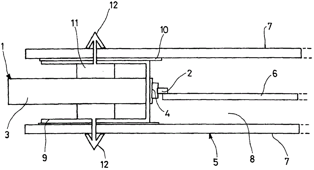
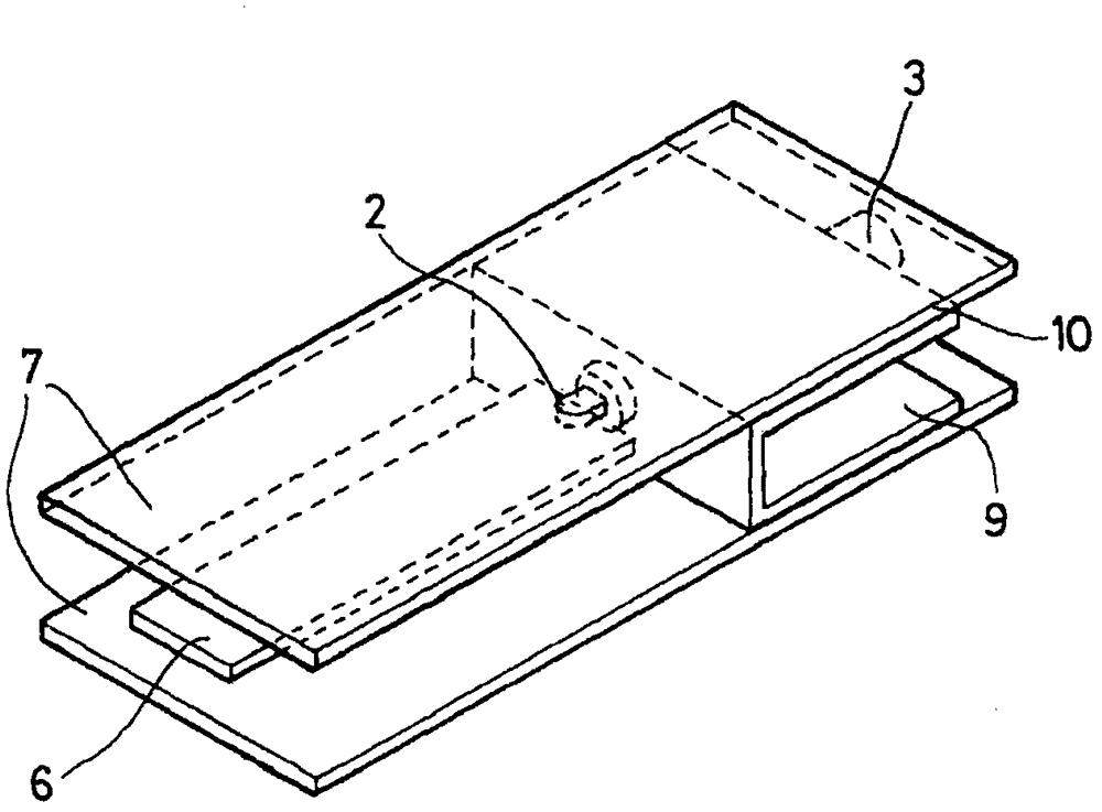
[0052] exist figure 1 and 2 In the embodiment of the mechanical and electrical connection device according to the invention shown schematically above, a coaxial cable 1 comprises a central inner conductor 2 made of metal, an outer conductor 3 receiving an alternating current (often implemented as metal or metal-plated braid) and a layer 4 of dielectric material between the two conductors 2,3. The cable 1 is connected to a multilayer stripline 5 comprising a conductive track 6 sandwiched between two conductive surfaces 7 . The ground metal or metal-plated conductive surface 7 forms the ground plane of the multilayer line 5 . A dielectric layer 8, which in this case consists of air and provides electrical isolation, separates the conductive tracks 6 from the conductor surfaces 7 located on either side. The inner conductor 2 of the coaxial cable 1 is electrically connected to the conductive track 6 of the multilayer line 5, for example by means of welding. The mechanical and el...


PUM


Abstract

The invention relates to a device for the mechanical and electrical connection between a multilayer line comprising at least one conducting track and at least one ground plane and a coaxial cable comprising an inner conductor and an outer conductor transmitting high-frequency signals, the mechanical and the electrical connection apparatus comprising: means for electrically connecting a coaxial cable to a ground plane of a multilayer line, comprising a conductive surface disposed opposite the ground plane of the multilayer line, wherein a layer of dielectric material isolates the ground plane from the conductive surface so as to A capacitive electrical link is established between the conductive surface and the ground plane; and a mechanical securing means comprising at least one raised pattern made of a dielectric material insertable into a suitable opening formed in the ground plane.

Description

technical field [0001] The present invention relates to a device for mechanical and electrical connection between a coaxial cable carrying high frequency signals and a line comprising multilayer microstrip or stripline. This mechanical and electrical connection device may eg be part of a radio frequency module installed in the base station equipment room. Background technique [0002] In the case of a microstrip type configuration, a grounded conductive surface commonly referred to as a "ground plane" is arranged on one side of a planar dielectric substrate. Conductive tracks are secured to the other side of the dielectric substrate. Microstrip lines usually take the form of printed circuits deposited on one side of a dielectric substrate whose opposite metallized ground plane forms the ground plane. [0003] In a stripline configuration, two continuous ground conductor plates are arranged in parallel on either side of the conductive track. A dielectric layer insulates ea...

Claims


Application Information

Patent Timeline
Patent Type & Authority Patents(China)
IPC IPC(8): H01P5/08H01P3/08
CPCH01P3/085H01P5/085
Inventor J-P·阿雷尔P·勒康G·雅各布
Owner ALCATEL LUCENT SAS
Learn More