Dust cup of dust collector and dust collector

A vacuum cleaner and dust cup technology, which is applied in the field of cleaning appliances, can solve the problem of low dust separation efficiency of the dust cup, achieve good dust separation effect, good effect, and avoid dust.

Inactive Publication Date: 2012-02-01
JIANGSU MIDEA CLEANING APPLIANCES
View PDF8 Cites 17 Cited by
  • Summary
  • Abstract
  • Description
  • Claims
  • Application Information

AI Technical Summary

Problems solved by technology

[0006] The problem solved by the invention is the problem of low dust separation efficiency of the dust cup of the existing vacuum cleaner

Method used


Image

  • Dust cup of dust collector and dust collector
  • Dust cup of dust collector and dust collector
  • Dust cup of dust collector and dust collector

Examples


Embodiment Construction

[0027] In order to illustrate the technical content, structural features, achieved goals and effects of the present invention in detail, the following will be described in detail in conjunction with the embodiments and accompanying drawings.

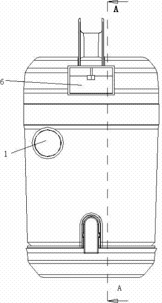
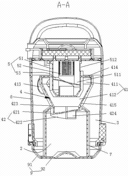
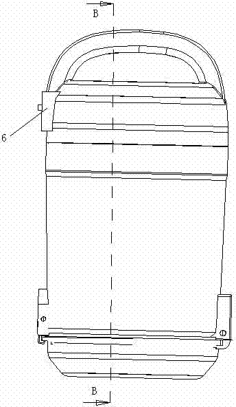
[0028] see Figure 1 to Figure 4 The dust cup of the vacuum cleaner according to the first embodiment of the present invention has an air inlet 1 , a primary dust collection chamber 2 , a secondary dust collection chamber 3 , a primary cyclone separator 4 , a secondary cyclone separator 5 and an air outlet 6 .

[0029] read on Figure 1 to Figure 4 , the primary cyclone separator 4 includes a primary cyclone chamber 41 and a primary cyclone channel 42 . The primary cyclone chamber 41 includes a cylindrical first receiving portion 411 and a conical second receiving portion 412 . The primary cyclone chamber 41 communicates with the air inlet 1, specifically, on the side wall of the primary cyclone chamber 41 (the side wall of the first r...


PUM


Abstract

The invention discloses a dust cup of a dust collector, and the dust cup is provided with an air inlet, a primary dust collection chamber, a secondary dust collection chamber, a primary cyclone separator, a secondary cyclone separator and an air outlet, wherein the secondary dust collection chamber surrounds the primary dust collection chamber; the primary cyclone separator is provided with a primary cyclone channel; the primary cyclone channel comprises a surrounding wall and a baffle; the baffle is spirally extended to the bottom, used for receiving crush as, of the primary dust collection chamber from the bottom of the cyclone chamber so as to form the spirally-extending primary cyclone channel together with the surrounding wall; one end, serving as a crude ash inlet, of the primary cyclone channel is communicated with the primary cyclone chamber; the other end, serving as a primary ash outlet, of the primary cyclone channel is communicated with the primary dust collection chamber;the secondary cyclone separator comprises a cyclone in which a secondary cyclone channel is arranged; the inlet of the secondary cyclone channel is communicated with the primary cyclone chamber, is positioned above the crude ash inlet and is opposite to the crude ash inlet; and the outlet of the secondary cyclone channel is communicated with the air outlet and the secondary dust collection chamber. According to the invention, the crude ash in dust can be prevented from rising, and dust and ash can be excellently separated with high efficiency.

Description

[0001] technical field [0002] The invention relates to a cleaning appliance, in particular to a vacuum cleaner, in particular to a dust cup of the vacuum cleaner. Background technique [0003] Chinese patent application No. 200920184866.7 discloses a vacuum cleaner, which includes a primary cyclone separator, a plurality of secondary cyclone separators arranged side by side, the primary cyclone separator is located in the secondary cyclone separator Upstream of the primary cyclone separator, the primary cyclone separator includes a primary cyclone bucket, a primary dust collection chamber located below the primary cyclone bucket, and a primary deflector column arranged inside the primary cyclone bucket. The barrel wall of the primary cyclone barrel has a primary air inlet and a primary ash outlet in a direction tangent to the inner wall of the barrel, and the primary ash outlet is located below the primary guide column and along the It is set along the tangential directio...

Claims


Application Information

Patent Timeline
Patent Type & Authority Applications(China)
IPC IPC(8): A47L9/16
Inventor 朱利清
Owner JIANGSU MIDEA CLEANING APPLIANCES
Why Eureka
Try Eureka