
Environment-friendly dust-free vibration screen

A vibrating sieve, environmental protection technology, applied in the direction of filter screen, grille, separating solids from solids with air flow, etc., can solve the problems of small workload, inability to drop grain, complex structure, etc., achieve good effect and solve dust Phenomenon, the effect of improving air quality

Inactive Publication Date: 2018-06-22
界首市金龙机械设备有限公司
View PDF11 Cites 2 Cited by
  • Summary
  • Abstract
  • Description
  • Claims
  • Application Information

AI Technical Summary

Problems solved by technology

The device has complex structure, large volume, and small workload
[0004] Moreover, the above-mentioned design cannot realize the real-time transportation of grain, nor can it drop grain at a designated location, which reduces the actual convenience of operation

Method used


Image

  • Environment-friendly dust-free vibration screen
  • Environment-friendly dust-free vibration screen
  • Environment-friendly dust-free vibration screen

Examples


Embodiment 1

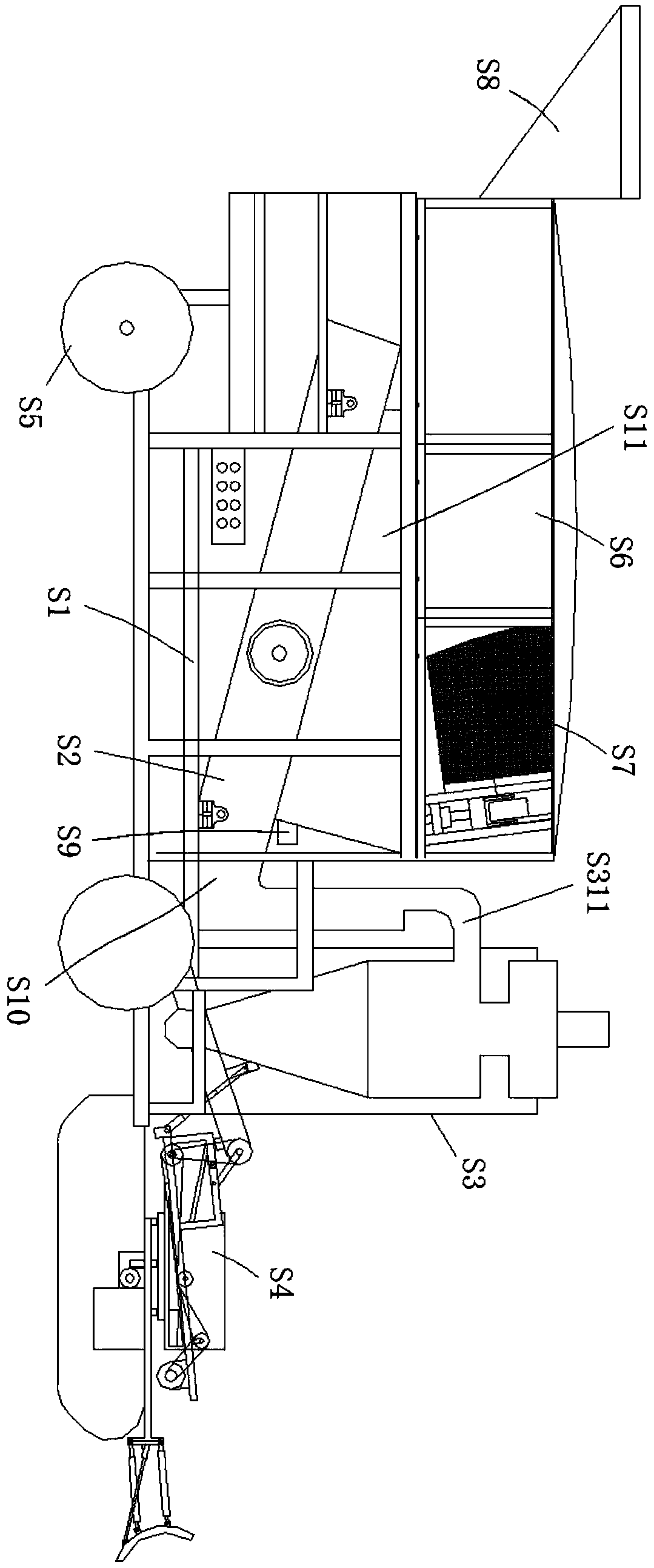
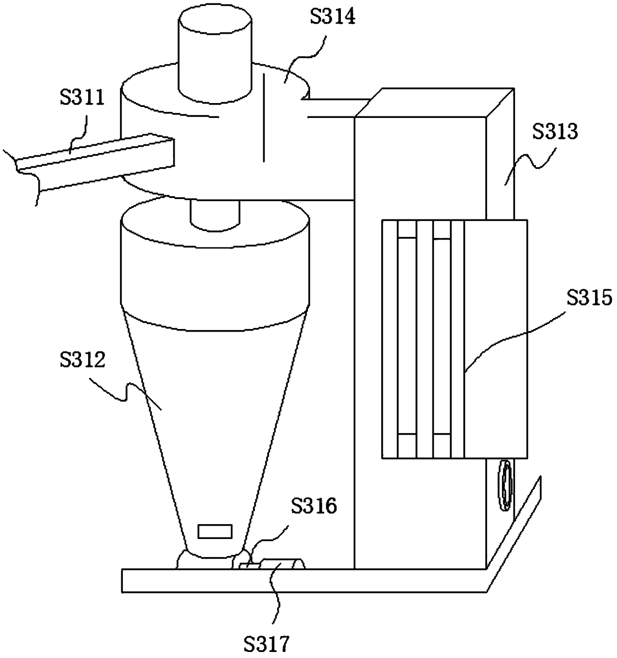
[0041] see figure 1 , an environment-friendly dust-free vibrating screen, comprising: a frame S1, a vibrating screen S2, a dust removal assembly S3 and a grain transportation assembly S4, the bottom of the frame S1 is equipped with a walking wheel S5, and the upper part of the frame S1 is provided with Outer shell S6, a spiral screen S7 is horizontally installed in the outer shell S6, a rotating shaft is installed in the spiral screen S7, a driving motor is connected to one end of the rotating shaft, and the driving motor drives the rotating shaft to rotate, thereby driving The spiral screen S7 rotates, and one end of the spiral screen S7 is connected with a grain feeding hopper S8, the vibrating screen S2 is arranged under the outer shell S6, and the grain feeding end surface of the vibrating screen S2 passes through the grain feeding channel S11 and the outer shell. The spiral screen S7 in the body S6 is connected, so that the clean grain falling from the spiral screen S7 ca...

Embodiment 2

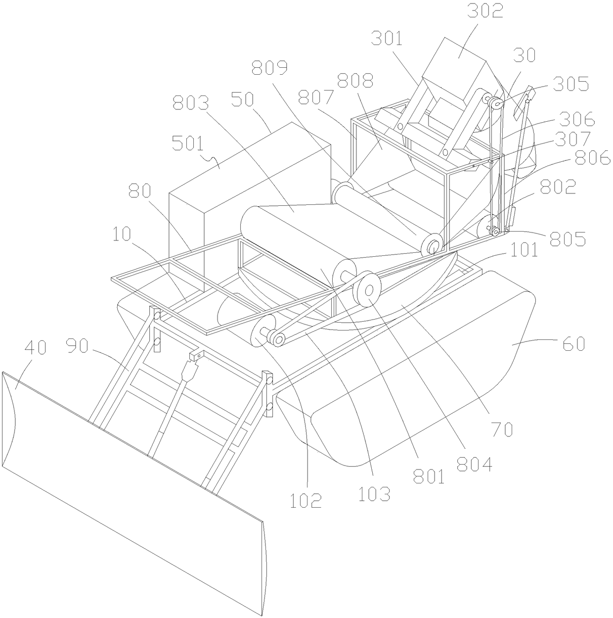
[0044] see Figure 3-7 , on the basis of Embodiment 1, the grain transport assembly is improved, wherein the grain transport assembly includes: an underframe assembly 10, a first drive motor 101, a grain transport auger 30, a grain push shovel 40, a control system 50 and the driving wheel 60, the control system 50 is installed in a box body 501, and the box body 501 is fixed on the upper position of one side of the chassis assembly 10, and the chassis assembly 10 is made of aluminum alloy and has a square structure; the first The driving motor 101 is installed at the bottom of the chassis assembly 10, and the driving wheels 60 are installed on both sides of the chassis assembly 10, and the driving wheels 60 are powered by the first driving motor 101. The driving wheels 60 adopt a crawler structure, and the power is strong. The driving is barrier-free, and the track is a rubber track, which will not crush the grain. A turntable 70 is installed on the chassis assembly 10, and a...

Embodiment 3

[0057] On the basis of embodiment 2, the control system is designed as a remote control type, the control system includes a remote controller, an infrared receiver and a processor, the infrared receiver and the processor are installed in the box, the infrared emitter in the remote controller and the infrared The receiver communicates through infrared rays, the infrared receiver is connected to the processor, and the processor is connected to the first drive motor, the second drive motor, the first push rod motor and the second push rod motor to realize remote control operation.


PUM


Abstract

An environment-friendly dust-free vibration screen comprises a machine frame, a vibration screen body, a dedusting assembly and a grain conveying assembly. Travelling wheels are mounted at the bottomof the machine frame. An outer shell is arranged on the upper portion of the machine frame. A spiral screen cloth is horizontally mounted in the outer shell. A rotary shaft is mounted in the spiral screen cloth. One end of the rotary shaft is connected with a driving motor. The rotary shaft is driven by the driving motor to rotate, and thus the spiral screen cloth is driven to rotate. A grain feeding hopper is connected with one end of the spiral screen cloth. The vibration screen body is arranged on the lower portion of the outer shell. The grain feeding inlet end face of the vibration screenbody communicates with the spiral screen cloth in the outer shell through a grain inlet channel, and thus pure grain falling down from the spiral screen cloth can fall onto the vibration screen body.A big impurity channel is arranged at the front end of the spiral screen cloth. The vibration screen body is obliquely arranged. A grain outlet channel is arranged at the lower end of the vibration screen body. The dedusting assembly is connected to the upper portion of the grain outlet channel. The grain conveying assembly is arranged on the lower portion of the grain outlet channel. The screened pure grain can be sent to assigned places through the grain conveying assembly.

Description

technical field [0001] The invention relates to the technical field of grain machinery, in particular to an environment-friendly and dust-free vibrating screen. Background technique [0002] The grain cleaning machines currently on the market for cleaning grain are mainly composed of hoppers, fans, cyclone dust collectors, discharge outlets, and stands. The fine debris, use the negative pressure air flow to clean up the debris to achieve the purpose of cleaning the grain. Although the grain cleaning machine in the prior art can screen out large and small impurities, its screening effect is not good, and the effect of leveling the material is not good. It uses the gravity of the grain itself to come out of the discharge port, which sometimes leads to blockage of the discharge port. , so that the amount of grain screening is reduced and the work efficiency is low. [0003] For example, the authorized announcement number CN101934272A relates to a large-scale cylinder grain cl...

Claims


Application Information

Patent Timeline
Patent Type & Authority Applications(China)
IPC IPC(8): B07B9/00B07B1/22B07B1/28B07B1/42B07B1/46B07B7/08B01D50/00
CPCB07B1/22B07B1/28B07B1/42B07B1/4609B07B7/08B07B9/00B01D50/20
Inventor 于素华申梦婷申自辉
Owner 界首市金龙机械设备有限公司
Learn More