
Bending molding structure for stamping mould

A technology of bending forming and stamping dies, which is applied in the field of stamping dies, can solve the problems of low processing efficiency, low processing precision, and high production cost, and achieve the effects of improving processing efficiency, improving processing accuracy, and ensuring quality

Active Publication Date: 2012-02-01
PERLMAN ELECTRICAL KUSN
View PDF4 Cites 8 Cited by
  • Summary
  • Abstract
  • Description
  • Claims
  • Application Information

AI Technical Summary

Problems solved by technology

[0003] At present, in the stamping process, for the bending and forming of the product, especially the bending process that requires a negative angle, the existing stamping forming mold is generally completed in three stations: (1) First, the product is bent into a 45 degrees; (2), then continue to stamp the product folded into 45 degrees to 90 degrees, (3), and finally stamp the product into the required negative angle, that is, an angle greater than 90 degrees; this kind of bending stamping mold , not only expensive, but also complex operation, many processing procedures, time-consuming and labor-intensive, low processing efficiency, and it is difficult to change the size of the negative angle of stamping according to customer needs in the stamping process. The cost is high, and it is difficult to achieve the quality quality required by the product

Method used


Image

  • Bending molding structure for stamping mould
  • Bending molding structure for stamping mould
  • Bending molding structure for stamping mould

Examples


Embodiment

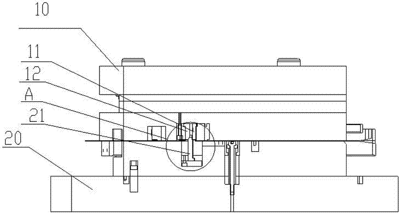
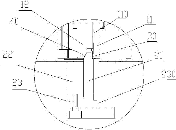
[0023] see figure 1 with figure 2 , the bending forming structure for the stamping die of the present embodiment, which includes an upper mold 10 and a lower mold 20 adapted to the upper mold 10, the lower mold 20 is provided with a mold core 22 that can float up and down and is installed under the mold core 22 The mold core fixing plate 23, the lower end surface of the mold core fixing plate 23 is processed with an installation groove 230, a swingable movable insert 21 is installed on the lower mold 20 through the installation groove 230, and the upper mold 10 is fixed with a movable insert 21 The matching bending punch 11 and the angle punch 12 that controls the swing angle of the movable insert 21.

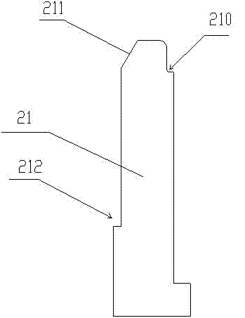
[0024] In this example, see image 3 , the lower end of the movable inlet 21 is "L"-shaped, and is movably installed in the installation groove 230; the upper end of the movable inlet 21 passes through the mold core 22 and is inserted into the mold cavity on the mold core 22...


PUM


Abstract

The invention relates to a bending molding structure for a stamping mould, which comprises an upper mould and a lower mould which is matched with the upper mould, wherein an oscillatory moveable insert is arranged on the lower mould; a bending stamping head which is matched with the oscillatory moveable insert is arranged on the upper mould; when the upper mould and the lower mould are closed, anangle bending slot which is used for realizing the bending of a product is formed between the bending stamping head and the oscillatory moveable insert; and an angle stamping piece which is used for controlling an oscillating angle of the oscillatory moveable insert is arranged on the upper mould. By adopting the bending molding structure provided by the invention, the negative angle bending molding of the product is realized, the purpose of once stamping negative angle bending molding of the product is realized and different demands on the machine-shaping with a bending angle are met. The bending molding structure has the advantages that the bending angle is conveniently adjusted, operation is simple, only once stamping is needed, tolerance caused by more than once stamping is avoided, processing precision of the product is promoted, quality of the product is ensured, operation is concise and simple, maintenance is conveniently realized, cost is low, time and labor are saved and processing efficiency is promoted.

Description

technical field [0001] The invention relates to a stamping die, in particular to a bending forming structure for the stamping die. Background technique [0002] The status of the mold industry in the national economy is rising day by day. Mold is the basic process equipment for industrial production. In products such as electronics, automobiles, motors, electrical appliances, instruments, home appliances and communications, 60% to 80% of the parts rely on molds. Forming, especially metal thin material bending processing products are widely used in IT communication electronics, electrical appliances and automobile manufacturing. Therefore, the quality of molds directly determines the quality of products. [0003] At present, in the stamping process, for the bending and forming of the product, especially the bending process that requires a negative angle, the existing stamping forming mold is generally completed in three stations: (1) First, the product is bent into a 45 degr...

Claims


Application Information

Patent Timeline
Patent Type & Authority Applications(China)
IPC IPC(8): B21D37/10
Inventor 刘毅
Owner PERLMAN ELECTRICAL KUSN
Learn More