
Open end wrench capable of being wrenched to and fro

A technology of open-end wrench and slider, which is applied in the field of open-end wrench, can solve problems such as unsmooth structure operation, and achieve the effect of improving stability

Active Publication Date: 2012-02-01
胡厚飞
View PDF13 Cites 2 Cited by
  • Summary
  • Abstract
  • Description
  • Claims
  • Application Information

AI Technical Summary

Problems solved by technology

[0009] In view of the deficiencies of the prior art, the object of the present invention is to provide a reciprocating open-end wrench to solve the problem of unsmooth operation of the existing structure

Method used


Image

  • Open end wrench capable of being wrenched to and fro
  • Open end wrench capable of being wrenched to and fro
  • Open end wrench capable of being wrenched to and fro

Examples


Embodiment Construction

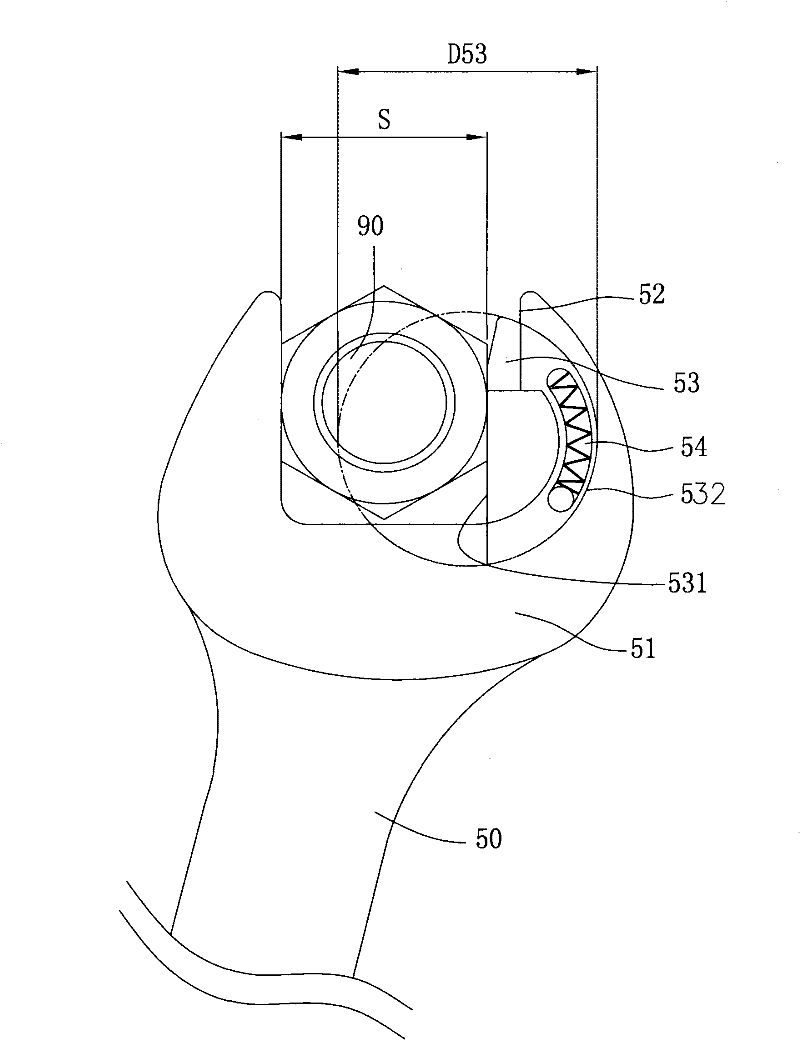
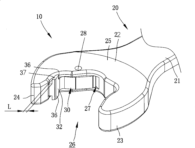
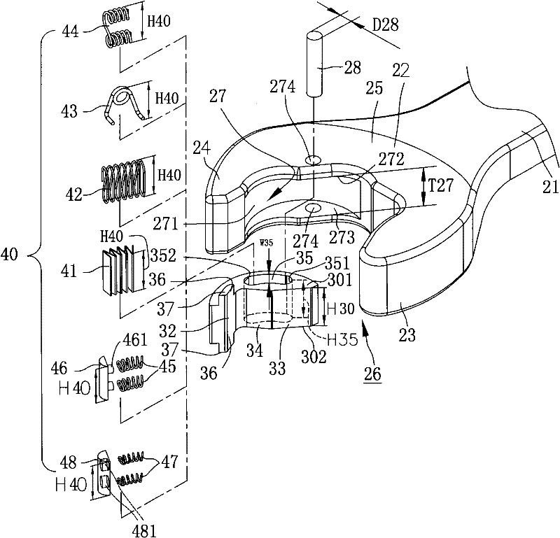
[0064] Regarding the technology, means and effects thereof adopted in the present invention, a preferred embodiment is given and described in detail in conjunction with the drawings as follows, with reference to Figure 2 to Figure 4 ,as well as Figure 7 to Figure 12 The open-end wrench 10 of the present invention includes a body 20 , a slider 30 and an elastic device 40 ; wherein: the body 20 has a grip portion 21 and a jaw 22 disposed at the front end of the grip portion 21 . Jaw 22 can connect working object 90, such as the hexagonal head of a bolt. When the working object 90 is a hexagonal head of a bolt, the six force-bearing surfaces are arranged counterclockwise in a ring at the six o'clock direction of the hexagonal head. Similarly, a positive force-bearing surface 91A to a sixth positive force-bearing surface 96A also have a first reverse force-bearing surface 91B to a sixth reverse force-bearing surface 96B. The user can hold the grip portion 21 and turn the body 2...


PUM


Abstract

The invention discloses an open end wrench capable of being wrenched to and fro. The open end wrench comprises a body which is provided with a grip jaw; a sliding chute is formed in the grip jaw; a chute body of the sliding chute can be processed at one time; a sliding block can slide along an arc in the sliding chute and is provided with a guide slot through which a guide column can pass to ensure a structure is reinforced and does not fall off easily; two sides of a first wrenching plane of the sliding block are provided with a first expanding surface respectively; a first jaw and a second jaw of the clamping jaw, the first wrenching plane of the sliding block and an inner circle diameter formed between two expansion surfaces can rotate relative to an axis position of a working substance and do not generate clamping interference; and the areas of the expansion surfaces of the two sides of the sliding block are expanded outward from the first wrenching plane to two side walls of a first support wall and a second support wall of the body, so the contact area of the first wrenching surface and a fourth forward-direction stress surface of the contacted working substance is increased.

Description

technical field [0001] The invention relates to an open-end wrench, in particular to an open-end wrench which can be turned on a working object and can be reciprocally wrenched relative to the axial center of the working object. Background technique [0002] Among the existing structural designs related to the technical field to which the present invention belongs, there was previously the structural design of U.S. No. 1,320,668. The wrench revealed a stationary jaw and a movable jaw, and the movable jaw passed through a spring. ) to push back and forth on the guide rail (guide). When the user wants to turn the nut, turning the wrench allows the fixed claw and the movable claw to drive the nut to rotate. When the user intends to move the wrench to the next turning position, turning the wrench in the opposite direction can make the movable claw retreat and compress the spring without driving the nut to rotate. The effect of locking or loosening the nut can be achieved by re...

Claims


Application Information

Patent Timeline
IPC IPC(8): B25B13/08B25B13/58
Inventor 胡厚飞
Owner 胡厚飞
Learn More