Blade swirl-type dilution mixer for gas drainage

A blade swirl and gas extraction technology, which is applied in the field of ultra-low concentration methane thermal countercurrent oxidation and low-density energy recovery, can solve the problems of large flow resistance, increased energy consumption of transport gas, complex structure, etc., and avoid friction explosion. , The effect of reducing transmission power consumption and cost

Active Publication Date: 2013-04-10
SHANDONG UNIV OF TECH
View PDF2 Cites 1 Cited by
  • Summary
  • Abstract
  • Description
  • Claims
  • Application Information

AI Technical Summary

Problems solved by technology

[0004] In the patent "Oxidation Device Gas Mixing Intake System" (CN200920025062.2), the design of the main pipe and auxiliary pipe of the gas mixer is relatively complicated, and the high-concentration gas enters the gas from a very thin auxiliary pipe within 360° Intake main pipe increases the risk of explosion due to friction between high-concentration gas and wall surface
In the patent "Mixer for Coal Mine Drainage Gas and Vacuum Gas" (CN 201010274136.3), the structure of the mixer is complicated and the conical tailpipe of the gas injection pipe with evenly distributed small holes will bring great flow resistance. Increased energy consumption for transporting gas
In addition, there is no gas dilution mixer with relatively complete structure and performance.

Method used


Image

  • Blade swirl-type dilution mixer for gas drainage
  • Blade swirl-type dilution mixer for gas drainage
  • Blade swirl-type dilution mixer for gas drainage

Examples


Embodiment Construction

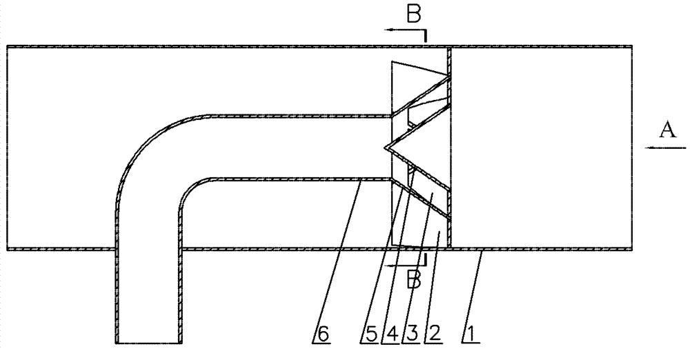
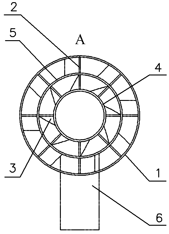
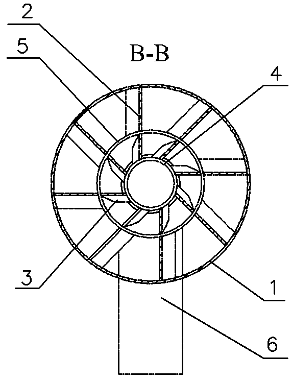
[0020] exist Figure 1-3 In the shown embodiment: it includes a tubular casing 1, a gas injection pipe, an inner deflection vane 3, an outer deflection vane 2, and a guide cone 4, and the gas injection pipe includes an inlet pipe 6 and a gas outlet installed at the outlet end of the inlet pipe 6. Expansion tube 5, wherein the pipe diameters of housing 1 and inlet pipe 6 are constant, expansion tube 5 adopts a variable diameter tube with gradually larger inner diameter, and the expansion angle is 60°, and the cross-sectional area of ​​the outlet end of expansion tube 5 is the cross-sectional area of ​​housing 1 65%, the axial distance between the outlet end and the outlet end of the housing 1 is three times the diameter of the housing 1, the inlet pipe 6 is a 90° elbow, and the axial distance between the elbow and the outlet end of the expansion tube 5 The distance is 8 times the diameter of the inlet pipe 6, the inlet end of the inlet pipe 6 is set outside the housing 1, the s...


PUM


Abstract

The invention relates to a blade swirl-type dilution mixer for gas drainage, and the mixer provided by the invention comprises a tubular shell and a gas ejector tube. The gas ejector tube comprises an inlet tube and an expanding tube arranged at the outlet end of the inlet tube, wherein the inlet tube is a 90-degree bent tube and the inlet end is arranged outside the shell; the straight tube section, close to the inlet end, of the inlet tube vertically penetrates into the shell, and the straight tube section, close to the outlet end, of the inlet tube is horizontally arranged in the shell; and the inlet tube is connected with the expanding tube and faces towards the outlet end of the shell. The blade swirl-type dilution mixer is characterized in that an inner deflection blade, an outer deflection blade and a diversion cone are additionally arranged; the diversion cone is of a cone structure and is arranged in the expanding tube, and the tip of the diversion cone is back to the outlet end of the expanding tube; the axial lines of the straight tube section, close to the outlet end, of the inlet tube, the expanding tube and the diversion cone are positioned at the axis of the shell; the inner deflection blade is arranged in a cavity defined by the inner wall of the expanding tube and the outer wall of the diversion cone; and the outer deflection blade is arranged in a cavity defined by the outer wall of the expanding tube and the inner wall of the shell. The blade swirl-type dilution mixer has the advantages of simple structure, uniform mixing and low energy consumption for gas drainage and transmission.

Description

technical field [0001] The present invention relates to the gas supply equipment of the coal mine exhaust gas oxidation device, in particular to a blade swirl dilution mixer for extracting gas, exhaust gas or air in the coal mine exhaust gas oxidation device, which belongs to the ultra-low concentration methane heat counterflow Oxidation and low-density energy recovery technology field. Background technique [0002] Globally, coal mining releases about 49Mt of methane every year, accounting for about 9% of the total global methane emissions. The concentration of methane in the atmosphere is the fastest growing among all greenhouse gases. Due to its strong greenhouse effect, the emission of methane must be effectively controlled. my country extracts more than 5 billion cubic meters of gas every year. Among them, only 1 / 4 to 1 / 3 of the drainage gas is used, and the rest are in the state of emptying. In particular, low-concentration drainage gas with a concentration of less ...

Claims


Application Information

Patent Timeline
Patent Type & Authority Patents(China)
IPC IPC(8): E21F7/00
Inventor 毛明明高振强刘永启刘瑞祥尤彦彦
Owner SHANDONG UNIV OF TECH
Why Eureka
Try Eureka