Spiral-flow type dilution mixer with adjustable blades for gas drainage

A blade swirling and gas extraction technology, which is applied in the field of ultra-low concentration methane thermal countercurrent oxidation and low-density energy recovery, can solve the problems of large flow resistance, increased energy consumption of transporting gas, complex structure, etc., and avoid friction explosion , reduce transmission power consumption, and reduce costs

Active Publication Date: 2013-09-18
SHANDONG UNIV OF TECH
View PDF6 Cites 0 Cited by
  • Summary
  • Abstract
  • Description
  • Claims
  • Application Information

AI Technical Summary

Problems solved by technology

[0004] In the patent "Oxidation Device Gas Mixing Intake System" (CN200920025062.2), the design of the main pipe and auxiliary pipe of the gas mixer is relatively complicated, and the high-concentration gas enters the gas from a very thin auxiliary pipe within 360° Intake main pipe increases the risk of explosion due to friction between high-concentration gas and wall surface
In the patent "Mixer for Coal Mine Drainage Gas and Vacuum Gas" (CN 201010274136.3), the structure of the mixer is complicated and the conical tailpipe of the gas injection pipe with evenly distributed small holes will bring great flow resistance. Increased energy consumption for transporting gas
In addition, there is no gas dilution mixer with relatively complete structure and performance.

Method used


Image

  • Spiral-flow type dilution mixer with adjustable blades for gas drainage
  • Spiral-flow type dilution mixer with adjustable blades for gas drainage
  • Spiral-flow type dilution mixer with adjustable blades for gas drainage

Examples


Embodiment Construction

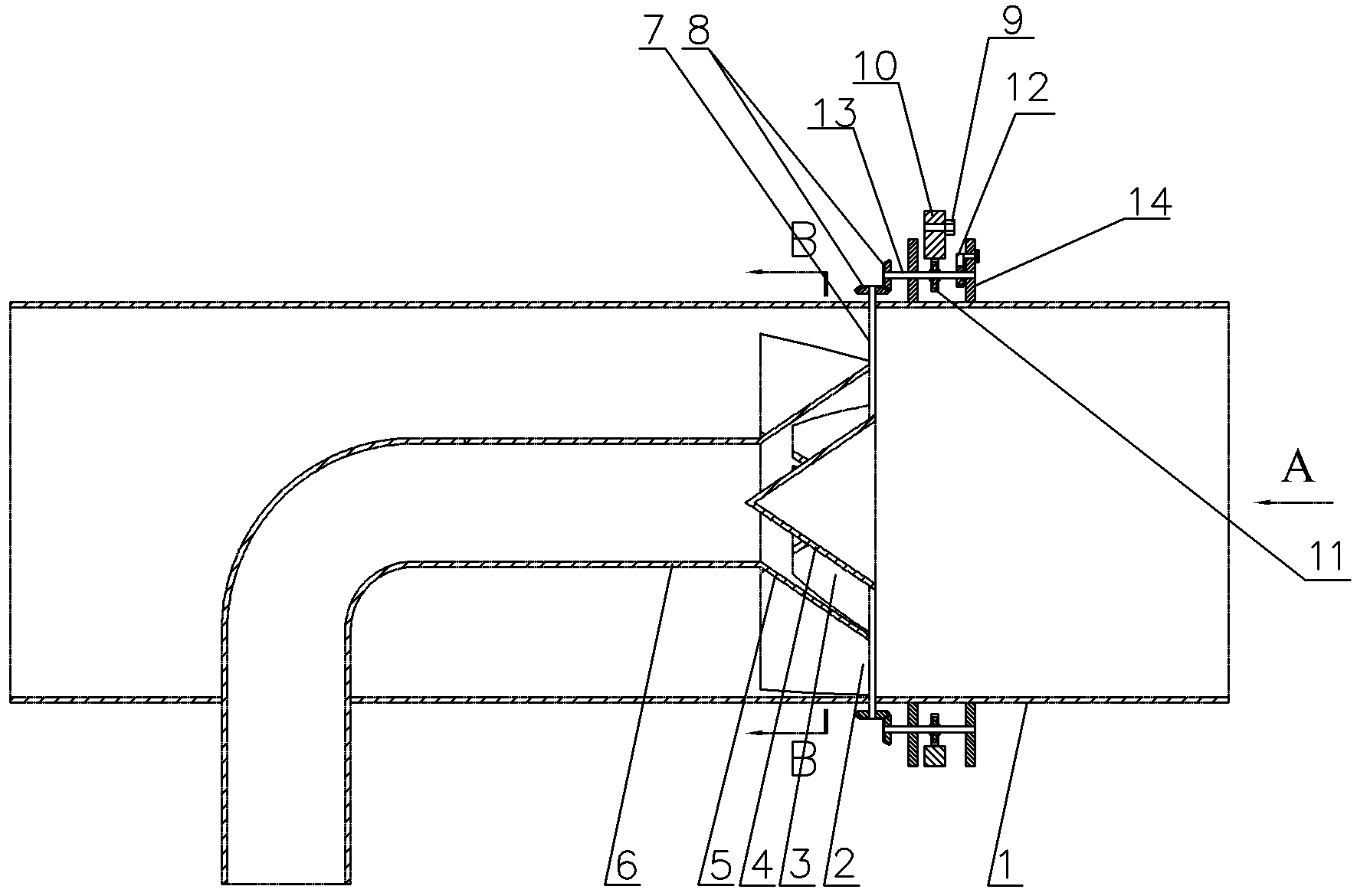
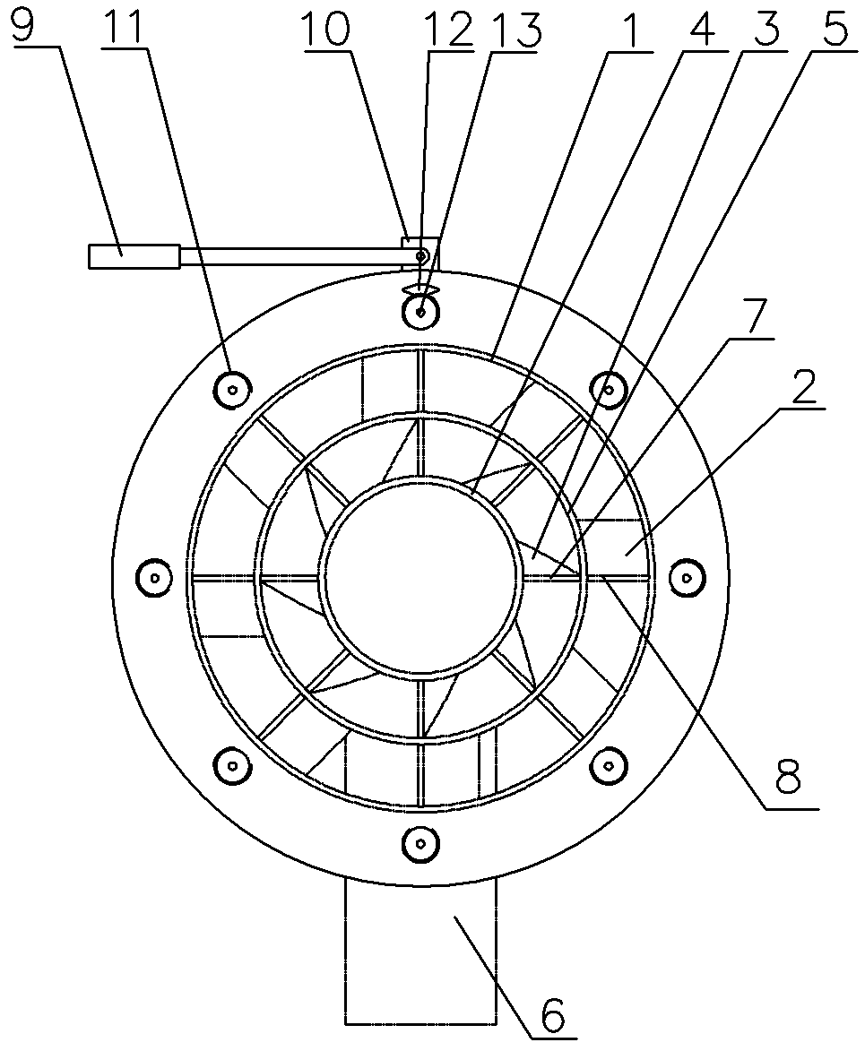
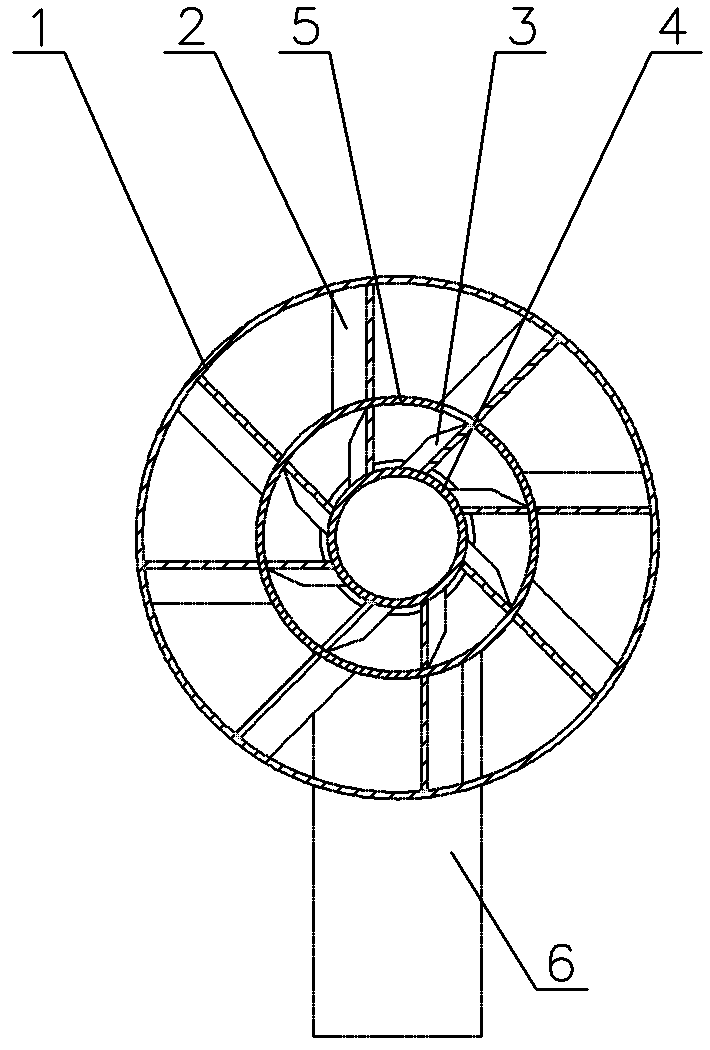
[0021] exist Figure 1-3 In the shown embodiment: it includes a tubular casing 1, a gas injection pipe, a guide cone 4, an inner deflection blade 3, an outer deflection blade 2, a blade adjustment mechanism and a bracket 14, and the gas injection pipe includes an inlet pipe 6 and The expansion tube 5 installed on the outlet end of the inlet pipe 6, wherein the inlet pipe 6 is a 90 ° elbow, the inlet end is arranged outside the housing 1, the straight pipe section of the inlet pipe 6 near the inlet end penetrates into the housing 1 vertically, and the straight pipe section near the outlet end The pipe section is horizontally arranged in the housing 1, connected with the expansion tube 5 and facing the outlet end of the housing 1; wherein the diversion cone 4 is located in the expansion tube 5, which is a cone structure, and its tip faces away from the outlet end of the expansion tube 5 The axis of the straight pipe section near the outlet end of the inlet pipe 6, the expansion ...


PUM


Abstract

The invention relates to a spiral-flow type dilution mixer with adjustable blades for gas drainage. The spiral-flow type dilution mixer comprises a tubular shell, an inlet pipe and an expansion pipe and is characterized in that a diverting cone, inward deflection blades, outward deflection blades, a blade adjusting mechanism and a support are additionally arranged, wherein the diverting cone is arranged in the expansion pipe; the inward deflection blades are arranged in a cavity between the inner wall of the expansion pipe and the outer wall of the diverting cone, and the outward deflection blades are arranged in a cavity between the outer wall of the expansion pipe and the inner wall of the shell; and in the blade adjusting mechanism, one end of an inward rotation shaft is arranged outside the shell, the other end of the inward rotation shaft is attached onto the outer wall of the diverting cone, the inward deflection blades are fixed on the inward rotation shaft, one end of the inward rotation shaft is fixedly provided with a driven gear of a bevel gear set, a drive gear in the bevel gear set is fixed on one end of an outward transmission shaft which is arranged on the support, an outer gear is fixed on the outward transmission shaft, and an outer adjusting handle is arranged on an outer gear ring meshed with the outer gear, of the outer gear. The spiral-flow type dilution mixer disclosed by the invention has the advantages of simple structure, uniformity in mixing, safety for protection, and low energy consumption for transmitting drained gas.

Description

technical field [0001] The present invention relates to the gas supply equipment of the coal mine exhaust gas oxidation device, in particular to a blade swirl dilution mixer for extraction gas and exhaust gas or air of the coal mine exhaust gas oxidation device, which belongs to the ultra-low concentration methane heat counterflow Oxidation and low-density energy recovery technology field. Background technique [0002] Globally, coal mining releases about 49Mt of methane every year, accounting for about 9% of the total global methane emissions. The concentration of methane in the atmosphere is the fastest growing among all greenhouse gases. Due to its strong greenhouse effect, the emission of methane must be effectively controlled. my country extracts more than 5 billion cubic meters of gas every year. Among them, only 1 / 4 to 1 / 3 of the drainage gas is used, and the rest are in the state of emptying. In particular, low-concentration drainage gas with a concentration of le...

Claims


Application Information

Patent Timeline
Patent Type & Authority Patents(China)
IPC IPC(8): E21F7/00B01F7/02B01F3/02B01F23/10
Inventor 毛明明高振强刘永启刘瑞祥尤彦彦
Owner SHANDONG UNIV OF TECH
Why Eureka
Try Eureka