Component structure of water pump seal element as well as automatic manufacturing mechanism and method thereof

A technology of water pump sealing and component structure, applied in pump components, manufacturing tools, machines/engines, etc., can solve problems such as the improvement of viscose manufacturing technology, unstable manufacturing performance, and harsh environmental requirements, so as to increase manufacturing costs, Increase the effect of beautiful appearance, stable and reliable sealing performance

Inactive Publication Date: 2012-02-01
江家炜
View PDF6 Cites 2 Cited by
  • Summary
  • Abstract
  • Description
  • Claims
  • Application Information

AI Technical Summary

Problems solved by technology

Although a small number of domestic manufacturers of water pump seals produced pure manual viscose operation methods were replaced by most manufacturers' mechanical bonding combined with manual operation methods, this only represents a slight improvement in the domestic water pump seal viscose manufacturing technology.
However, the traditional water pump seal components combined with glue bonding have two biggest shortcomings.
However, this precis

Method used


Image

  • Component structure of water pump seal element as well as automatic manufacturing mechanism and method thereof
  • Component structure of water pump seal element as well as automatic manufacturing mechanism and method thereof
  • Component structure of water pump seal element as well as automatic manufacturing mechanism and method thereof

Examples


Embodiment 1

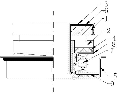
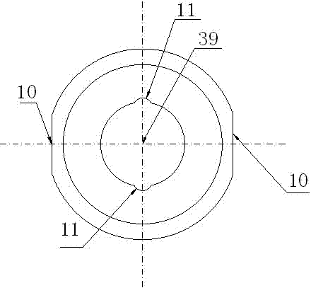
[0070] Such as figure 1 , 2 and 3, the structure of the water pump seal assembly of the present invention includes a moving ring 1, a static ring 2, a moving ring bushing 3, a rubber seal sleeve 4, a base cover 5, a moving ring 1 and a moving ring bushing 3 There is a moving ring sealing sleeve 6 between them, a rubber sealing sleeve 4 is set between the static ring 2 and the base sleeve 5, a spring 7 is set on the outer sleeve of the rubber sealing sleeve 4, and a washer 8 is provided between the top of the rubber sealing sleeve 4 and the spring 7 , the bottom of the rubber sealing sleeve 4 and the spring 7 are provided with a fixed seat reed 9, the outer circumference of the base cover 5 is symmetrically provided with 2 base cover cutouts 10, and the base cover middle hole 39 is symmetrically provided with 2 positioning ears 11, The outer circumference of the static ring 2 is symmetrically provided with 2 equal numbers of static ring cutouts 12 matched with the base cov...

Embodiment 2

[0072] Such as figure 1 , 4 As shown in and 5, the water pump seal assembly structure of the present invention is provided with three base cover cutouts 10 along the circumferential direction of the base cover 5, and an angle of 120 degrees is formed between adjacent base cover cutouts 10, and along the middle hole of the base cover 39 are provided with three positioning ears 11 in the circumferential direction, and an included angle of 120 degrees is formed between adjacent positioning ears 11; along the circumferential direction of the static ring 2, there are three static ring notches 12 matched with the base sleeve notch 10 , along the circumferential direction of the inner hole 40 of the static ring, there are three positioning ear grooves 13 matched with the positioning ears 11 of the base cover 5, and an angle of 120 degrees is formed between adjacent static ring cutouts 12 and adjacent positioning ear grooves 13 . All the other structures are with embodiment 1.

Embodiment 3

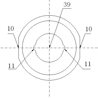
[0074] Such as figure 1 , 6 As shown in and 7, the water pump seal assembly structure of the present invention is provided with two base cover cutouts 10 along the circumferential direction of the base cover 5, and an angle of 60 degrees is formed between the two base cover cutouts 10, and along the middle hole of the base cover 39 is provided with two positioning ears 11 in the circumferential direction, and an included angle of 60 degrees is formed between the two positioning ears 11; along the circumferential direction of the static ring 2, there are two static ring notches 12 matched with the base sleeve notch 10 , an included angle of 60 degrees is formed between the two static ring cutouts 12, along the circumferential direction of the inner hole 40 of the static ring, there are two positioning ear slots 13 matching the positioning ears 11 of the base cover 5, two positioning ear slots 13 form an angle of 60 degrees. All the other structures are with embodiment 1.


PUM


Abstract

The invention discloses a component structure of a water pump seal element as well as an automatic manufacturing mechanism and method thereof. The structure comprises a moving ring, a stationary ring, a moving ring shaft sleeve, a rubber seal sleeve, a moving ring seal sleeve and a spring; a gasket is arranged between the top of the rubber seal sleeve and the spring; and a fixed seat spring sheetis arranged between the bottom of the rubber seal sleeve and the spring. The structure is characterized in that a plurality of base sleeve notches are arranged along the peripheral direction of a base sleeve according to arbitrary partition value of the circumference of the base sleeve; a plurality of positioning lugs are arranged along the peripheral direction of the middle hole of the base sleeve according to the arbitrary partition value of the middle hole of the base sleeve; stationary ring notches which are matched with the equal amount of the base sleeve notches along the peripheral direction of the stationary ring according to the arbitrary partition value of the circumference of the stationary ring; and positioning lug grooves which are matched with equal amount of the positioninglugs of the base sleeve along the peripheral direction of the inner hole of the stationary ring according to the arbitrary partition value of the circumference of the inner hole of the stationary ring. The structure provided by the invention has the advantages that the seal property is good, and the integral automatic manufacturing with high efficiency and high accuracy can be realized.

Description

technical field [0001] The invention relates to a pump seal assembly structure for water pumps. [0002] The invention also relates to an automatic manufacturing mechanism and an automatic manufacturing method for manufacturing the water pump seal component structure. Background technique [0003] At present, domestic manufacturers of automotive cooling pump water pump seals have completed the manufacture of water pump seal assemblies, and the main structure adopts a combination of two processes. [0004] The first method: at the joint between the static ring and the upper part of the rubber sealing sleeve, at the joint between the lower part of the rubber sealing sleeve and the base sleeve, and at the joint between the two places, glue bonding technology is required to achieve airtightness Sealing, this is a bonding method with glue technology. [0005] The above-mentioned first craft viscose technology applies foreign early manufacturing methods, and adopts the glue b...

Claims


Application Information

Patent Timeline
IPC IPC(8): F04D29/08B23P19/02
Inventor 江家炜江雪忠
Owner 江家炜
Why Eureka
Try Eureka