Gas valve device and gas stove with same

A gas valve, gas technology, applied in valve device, valve operation/release device, valve details, etc., can solve the problems of increasing manufacturing cost, reducing service life, hidden safety hazards, etc., to improve the degree of intelligent control and reduce safety hidden dangers and the effect of reducing mechanical wear

Inactive Publication Date: 2012-02-01
BSH ELECTRICAL APPLIANCES JIANGSU
View PDF5 Cites 13 Cited by
  • Summary
  • Abstract
  • Description
  • Claims
  • Application Information

AI Technical Summary

Problems solved by technology

It can be seen that there are two major drawbacks in the existing gas valve technology: first, the safety valve and the flow control valve are set separately, which not only increases the manufacturing cost, but also the control accuracy is not high; second, the control of the existing gas valve is still mechanical Control is the main focus. On the one hand, the degree of intelligent control is not high, which cannot meet the needs of high-end and special users. On the other hand, the mechanical or semi-mechanical control mode is easy to cause wear, which will affect the control accuracy and sensitivity and reduce the service life. At the same time, there is also a safety hazard of air leakage

Method used


Image

  • Gas valve device and gas stove with same
  • Gas valve device and gas stove with same
  • Gas valve device and gas stove with same

Examples


Embodiment Construction

[0044] In order to make the object, scheme and beneficial effect of the present invention more clear, the present invention will be further described below in conjunction with the accompanying drawings and preferred embodiments.

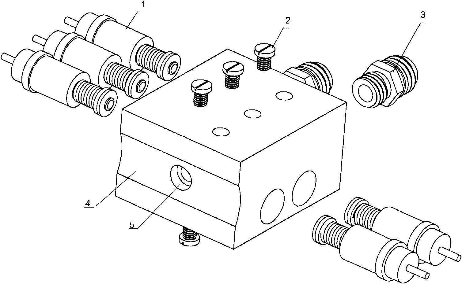
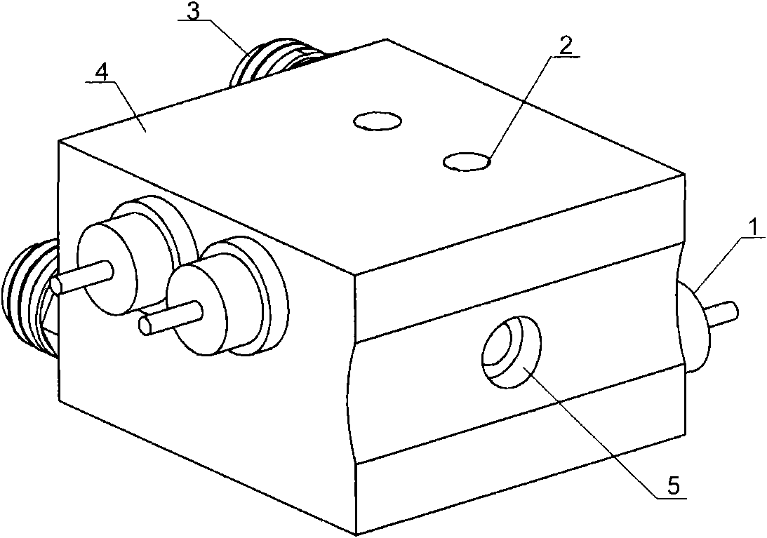
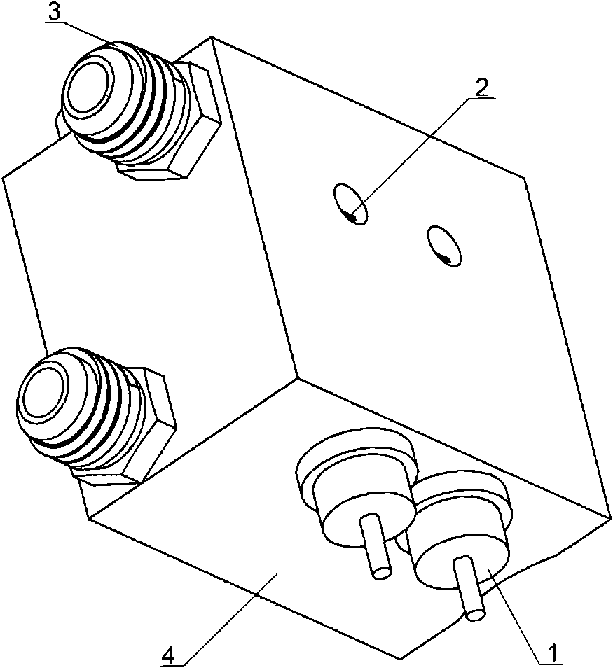
[0045] An example of a gas valve device proposed by the present invention Figures 1 to 6 As shown, it includes a gas inlet 5, a gas flow channel and a nozzle 3, the gas inlet 5 communicates with the main gas pipe, and the main gas pipe transports the gas to the gas inlet 5, and one end of the gas flow channel communicates with the gas inlet 5, and the gas flow The other end of the channel is connected with the nozzle 3, and the gas flowing in from the gas inlet 5 is delivered to the nozzle 3 after passing through the gas flow channel, and the nozzle 3 is used for supplying gas to the burner. The nozzle 3 includes a first nozzle and a second nozzle, the first nozzle is used to supply air to the small central flame cap of the burner, and the second no...


PUM


Abstract

The invention provides a gas valve device and a gas stove. The gas valve device provided by the invention comprises a gas inlet, a gas flow channel and a nozzle, wherein the gas inlet is mutually communicated with a main air pipe, and one end of the gas flow channel is communicated with the gas inlet; the other end of the gas flow channel is mutually communicated with the nozzle, the nozzle is used for supplying gas for a burner, and a self-opening electromagnetic valve is arranged in the gas flow channel; when the self-opening electromagnetic valve is opened, the gas passes through the self-opening electromagnetic valve so as to flow to the nozzle; when the self-opening electromagnetic valve is closed, the gas can not pass through the self-opening electromagnetic valve and flow to the nozzle; and the gas valve device also comprises a control module, and the control module is used for controlling the self-opening electromagnetic valve. The gas valve device provided by the invention has the advantages of improved intellectualized control degree of the gas, and prolonged service life.

Description

【Technical field】 [0001] The invention relates to the field of cookers and cooker parts, in particular to a gas valve device and a gas cooker. 【Background technique】 [0002] Existing gas valves include flow control valves and safety valves. When in use, the flow control valve and the safety valve must be turned on at the same time to ignite the gas cooker. Most of the current safety valves use electromagnetic spools, which are installed at the rear end of the flow control valve. When opening the flow control valve, the rotating shaft must be pressed down and then rotated to open the flow control valve. At the same time, the cam mounted on the rotating shaft rotates, and the solenoid valve is pushed open by the push rod. It can be seen that there are two major drawbacks in the existing gas valve technology: first, the safety valve and the flow control valve are set separately, which not only increases the manufacturing cost, but also the control accuracy is not high; seco...

Claims


Application Information

Patent Timeline
Patent Type & Authority Applications(China)
IPC IPC(8): F16K11/24F16K31/06F16K31/66F16K27/00F16K31/60F16K31/00F24C3/12
CPCF24C3/12
Inventor 博建安·克里斯丁邹雪
Owner BSH ELECTRICAL APPLIANCES JIANGSU
Why Eureka
Try Eureka