
Garbage feeding device

A technology for feeding device and garbage, applied in the direction of combustion method, combustion type, incinerator, etc., can solve the problems of arching, complex shape and size, clogging, etc., to prevent clogging or arching and ensure stable operation.

Inactive Publication Date: 2012-02-01
ANHUI CONCH KAWASAKI ENERGY CONSERVATION EQUIP +1
View PDF6 Cites 3 Cited by
  • Summary
  • Abstract
  • Description
  • Claims
  • Application Information

AI Technical Summary

Problems solved by technology

[0002] At present, garbage hoppers are installed in the upstream equipment of garbage incinerators in my country, and horizontal conveying equipment is installed on the lower side of the garbage hoppers. Blockage or even arching in the conveying equipment requires manual dredging, which not only increases the labor intensity of the operator, but also reduces the operating efficiency of the equipment

Method used


Image

  • Garbage feeding device
  • Garbage feeding device
  • Garbage feeding device

Examples


Embodiment Construction

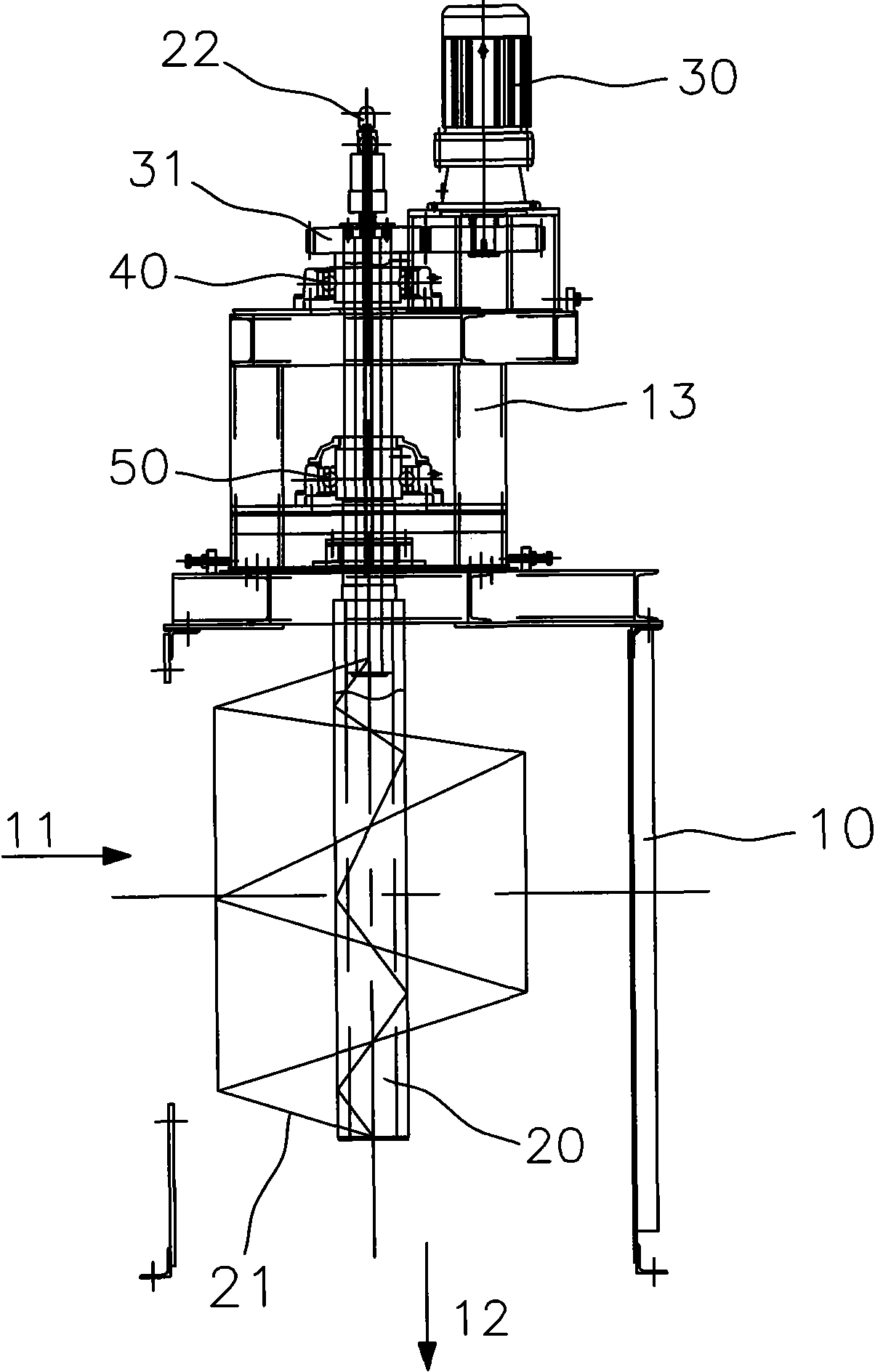
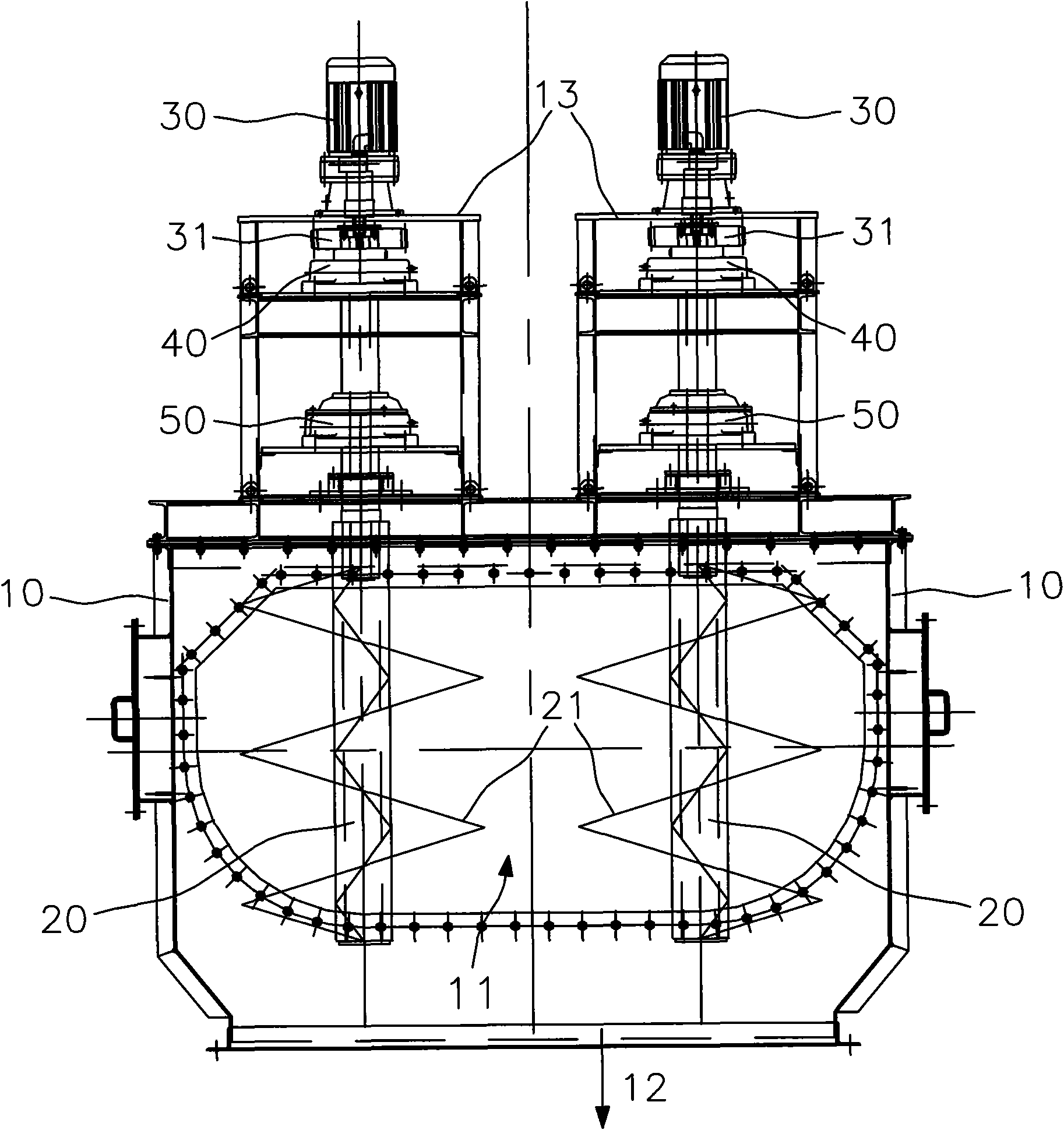
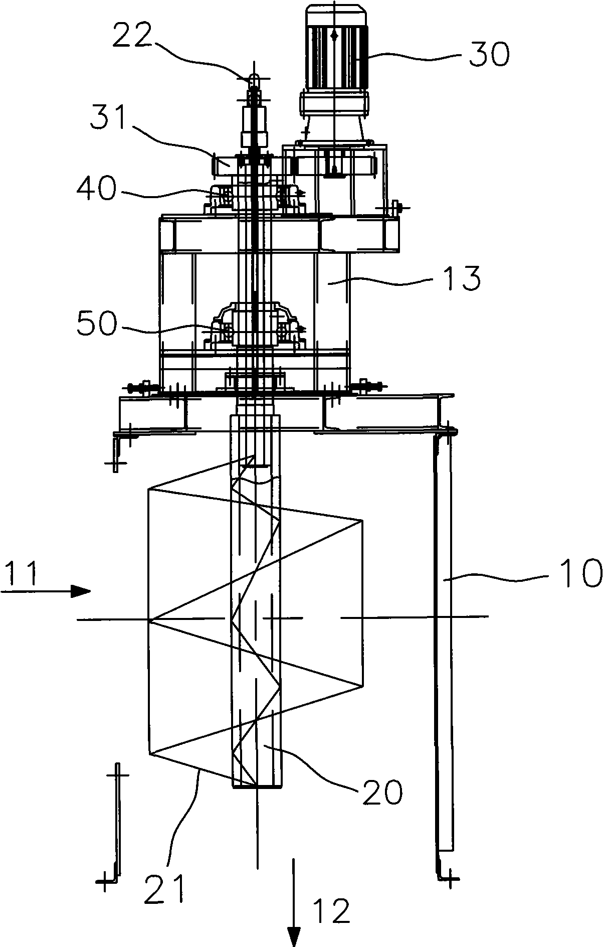
[0008] Such as figure 1 , 2 As shown, a garbage feeding device, the garbage feeding device includes a housing 10 with a cavity inside, the upper part of the outer surface of the housing 10 is provided with a feed port 11, and the lower side of the housing 10 is provided with a discharge Port 12, the cavity of the casing 10 is provided with a garbage crushing and conveying mechanism, and the garbage crushing and conveying mechanism is connected with the power mechanism arranged on the casing 10.

[0009] During actual operation, the housing 10 is fixed on the upper side of the garbage incinerator, and the garbage is input from the feed port 11 on the upper part of the housing. The crushed garbage enters the garbage incinerator for combustion through the discharge port 12 on the lower side of the housing.

[0010] Such as figure 1 , 2 As shown, the power mechanism includes a deceleration motor 30 arranged on the upper side of the housing 10. The deceleration motor 30 drives ...


PUM


Abstract

The invention relates to a garbage feeding device for feeding garbage into a garbage incinerator. The garbage feeding device comprises a shell, wherein a cavity is arranged inside the shell; a feeding hole is formed on the upper part of the outer side face of the shell; a discharge hole is formed on the lower part of the shell; a garbage crushing conveying mechanism is arranged in the cavity of the shell; and the garbage crushing conveying mechanism is connected with a power mechanism on the shell. From the above, in the garbage feeding device, the garbage crushing conveying mechanism is arranged in the shell, so that after materials are fed into the shell, the materials are scattered and crushed while being conveyed into the garbage incinerator, thereby greatly reducing and even eliminating a blocking or arching phenomenon of the garbage during a conveying process, and ensuring the stable running of a whole garbage treating system.

Description

technical field [0001] The invention relates to a garbage feeding device for feeding garbage incinerators. Background technique [0002] At present, garbage hoppers are installed in the upstream equipment of garbage incinerators in my country, and horizontal conveying equipment is installed on the lower side of the garbage hoppers. Blockage or even arching in the conveying equipment requires manual dredging, which not only increases the labor intensity of the operator, but also reduces the operating efficiency of the equipment. Contents of the invention [0003] The purpose of the present invention is to provide a garbage feeding device that can reduce or even eliminate the clogging or arching of garbage during the conveying process. [0004] In order to achieve the above object, the present invention adopts the following technical solutions: a garbage feeding device, the garbage feeding device includes a housing with a cavity inside, the upper part of the outer surface of...

Claims


Application Information

Patent Timeline
Patent Type & Authority Applications(China)
IPC IPC(8): F23G5/44
Inventor 纪勤应李大明汪宁李朝晖田云陈志全
Owner ANHUI CONCH KAWASAKI ENERGY CONSERVATION EQUIP
Learn More