Self-closing and anti-liquid impact device for air-cooled heat pump air conditioner

An air-cooled heat pump, self-closing technology, applied in refrigeration and liquefaction, refrigerators, refrigeration components, etc., can solve the problems of reducing evaporator pressure, compressor liquid shock failure, heating capacity attenuation, etc., to prevent liquid shock Troubleshooting, easy production operation, space-saving effect

Inactive Publication Date: 2012-02-01
林勇
View PDF0 Cites 8 Cited by
  • Summary
  • Abstract
  • Description
  • Claims
  • Application Information

AI Technical Summary

Problems solved by technology

[0002] The existing air-cooled heat pump air-conditioning system, in the winter heating work, due to the low outdoor ambient temperature, the heating capacity attenuates greatly, often cannot meet the requirements of the air-conditioning heat load, the temperature of the air-conditioned room decreases, and the comfort level decreases
At this time, the air-cooled heat pump air-conditioning system will increase the pressure of the condenser of the refrigeration system and reduce the pressure of the evaporator, so that the entire refrigeration system needs more refrigerant when heating than when cooling. When the working conditions change, there will be no evaporation. The liquid refrigerant returns to the compressor and is compressed, due to the incompressible characteristics of the liquid, it will cause the "liquid hammer" failure of the compressor
In order to prevent "liquid shock", the current air-cooled heat pump air-conditioning system installs a larger gas-liquid separator at the suction port of the compressor, which not only increases the cost, but also takes up space.

Method used


Image

  • Self-closing and anti-liquid impact device for air-cooled heat pump air conditioner
  • Self-closing and anti-liquid impact device for air-cooled heat pump air conditioner
  • Self-closing and anti-liquid impact device for air-cooled heat pump air conditioner

Examples


Embodiment Construction

[0015] combine figure 1 with figure 2 The specific embodiment of the present invention is further described:

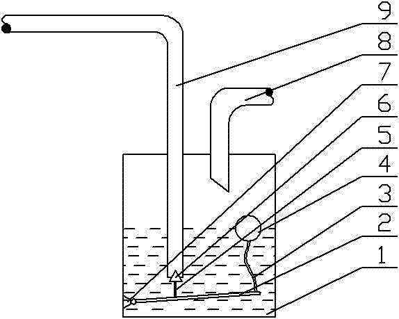
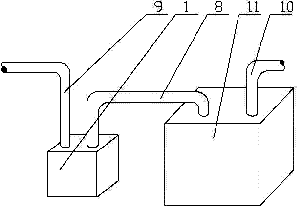
[0016] According to the technical solution provided by the present invention, an air-cooled heat pump air conditioner self-closing anti-liquid shock device includes a gas-liquid separator 1, a horizontal bar 2, a rope 3, a floating ball 4, a vertical bar 5, a valve core 6, a hinge 7, Output pipe 8, input pipe 9, compressor exhaust pipe 10, compressor 11, described compressor 11 is connected with condenser, throttle valve, evaporator, gas-liquid separator 1 sequentially in closed loop, described gas-liquid A hinge 8 is fixedly installed at the bottom of the inner side wall of the separator 1 , one end of the cross bar 2 is connected to the hinge 8 , and the other end is connected to the floating ball 5 by a rope 3 .

[0017] One end of the vertical rod 5 is fixedly connected to the cross bar 2 , and the other end is fixedly connected to the valve core 6 .

[0018] ...


PUM


Abstract

The invention relates to an anti-liquid impact device for a compressor, in particular to a self-closing and anti-liquid impact device for an air-cooled heat pump air conditioner. The self-closing and anti-liquid impact device comprises a gas-liquid separator, a cross rod, a rope, a floating ball, a vertical rod, a valve core, a hinge, an output pipe, an input pipe, a compressor exhaust pipe and a compressor, wherein the compressor is in closed-loop connection with a condenser, a throttling valve, an evaporator and the gas-liquid separator sequentially; the hinge is fixedly arranged at the bottom of the inner side wall of the gas-liquid separator; and one end of the cross rod is connected to the hinge, and the other end of the cross rod is connected with the floating ball by the rope. The anti-liquid impact device has the advantages that when liquid in the gas-liquid separator is too much, the input pipe is closed to prevent a liquid refrigerant from being absorbed into the compressor so as not to cause liquid impact; the size of the gas-liquid separator is reduced, manufacturing materials are saved, and the space is saved; and the anti-liquid impact device is easy to install and easy to produce and operate.

Description

technical field [0001] The invention relates to an anti-liquid shock device for a compressor, in particular to a self-closing anti-liquid shock device for an air-cooled heat pump air conditioner. Background technique [0002] The existing air-cooled heat pump air-conditioning system, in the winter heating work, due to the low outdoor ambient temperature, the heating capacity attenuates greatly, often cannot meet the requirements of the air-conditioning heat load, the temperature of the air-conditioned room decreases, and the comfort level decreases. At this time, the air-cooled heat pump air-conditioning system will increase the pressure of the condenser of the refrigeration system and reduce the pressure of the evaporator, so that the entire refrigeration system needs more refrigerant when heating than when cooling. When the working conditions change, there will be no evaporation. The liquid refrigerant returns to the compressor and is compressed, due to the incompressible ...

Claims


Application Information

Patent Timeline
Patent Type & Authority Applications(China)
IPC IPC(8): F25B49/02F25B43/00
Inventor 林勇
Owner 林勇
Why Eureka
Try Eureka